
Remote sensing is a multi-disciplinary activity that deals with the inventory, monitoring and assessment of natural resources, following the analysis of data obtained through observations from a remote platform. This technology, under development since the early 1960s, has shown great promise in improving the information collection regarding the world’s weather, environment and natural resources. The use of satellites as platforms for remote sensing has added another dimension to remote sensing. Satellites allow coverage of large areas at a time and repetitive coverage at predetermined intervals under similar sun illumination conditions using sun-synchronous orbits. This article describes the whole process of remote sensing, remote sensing satellites, sensors and various elements involved in space and ground segments. Special attention has been given to the configuration of the remote sensing satellites and ground station systems, and, wherever applicable, a comparison has been made with communication satellites systems.
Remote Sensing Process
Remote sensing is the technique of deducing information about an object, area or phenomenon through the analysis of data acquired by a sensor device that is not in physical contact with the sensed target. This definition is restricted to measurements made in different spectral regions of the interactions between the targets and electromagnetic (EM) radiations (such as light, heat and radio waves).
A fundamental property of an EM wave is that its velocity and wavelength change when it propagates through media of different densities. Its interaction with matter may, therefore, change the property of the incident wave, namely intensity, direction, wavelength, polarization and phase. The science of remote sensing records these changes and uses them to interpret the characteristics of the matter. The end-to-end process of remote sensing can be explained by the following stages/sequences: (1) a source of electromagnetic energy (sun/self emission), (2) transmission of energy from the source to the surface of the earth, wherein it also undergoes absorption and scattering during passage through the atmosphere, (3) interaction of electromagnetic radiations with the earth’s surface (reflection, scattering, absorption and re-emission), (4) transmission of the reflected/scattered/emitted energy from the objects/features of earth’s surface to the remote sensors mounted onboard (with appropriate modifications due to atmospheric effects), (5) sensor data output in digital electrical signal form, (6) modulation and transmission of the data (now called satellite payload data) to earth, (7) data acquisition through an earth station tracking receive antenna, (8) data demodulation and archival/recording in different media such as high density digital recorders, hard disks, digital cassette recorders, etc., (9) generation of products by processing of the data to different levels of accuracy employing various corrections and (10) interpretation of the data and its presentation into usable form such as floppies, maps, cartridges, discs, etc.
Remote Sensing Physics
The information from an object to the sensor is propagated by EM waves through the atmosphere at the velocity of light, directly through free space as well as indirectly by reflection, scattering and re-radiation. The interaction of EM waves with natural surfaces and the atmosphere is strongly dependent on the frequency of the waves. Remote sensing by satellites involves atmospheric degradation from the entire atmospheric column. Thus, the characteristics of the atmosphere significantly determine the effective use of the electromagnetic spectrum for remote sensing. Although the electromagnetic spectrum is infinitely wide and spans the entire region ranging from the longest wavelengths of radio waves to the shortest wavelengths corresponding to gamma rays, most of the regions cannot be used for remote sensing owing to certain practical limitations. X-rays and most of the ultraviolet radiations are rendered unusable by atmospheric attenuation (complete absorption by the ozone layer in the upper atmosphere), while at lower frequencies, the ionosphere reflects the radiations totally. Therefore, the spectral regions (also called atmospheric windows) in which the atmosphere is transparent or offers very little attenuation only can be used for remote sensing. Such windows fall in ultraviolet (0.3 to 0.4 µm), visible (0.4 to 0.75 µm), near infrared (0.77 to 1.34 µm), mid-infrared (1.55 to 2.44 µm), thermal-infrared (3.5 to 5 µm, 8 to 12.5 µm and 17 to 22 µm) and microwave (2 to 1000 mm) regions of the electromagnetic spectrum. The remaining non-usable spectral bands (other than the previously mentioned low attenuation atmospheric windows) offer severe attenuation/absorption due to the presence of water vapor (H2O), oxygen (O2), ozone (O3), carbon dioxide (CO2) and aerosols in the atmosphere. Figure 1 depicts the generalized absorption spectrum of the earth’s atmosphere.
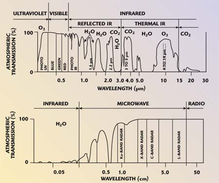
Fig. 1 Generalized absorption spectrum of the earth’s atmosphere.
Many earth surface materials respond in various distinctive ways (have different spectral reflectance characteristics) when illuminated by different regions of the electromagnetic spectrum. Moreover, within any limited region of the spectrum, a particular material exhibits a diagnostic spectral radiance pattern, which is generally different from that of another material. Thus, every individual substance or class of related substances has its own specific spectral signatures (ability to respond to an EM wave) or spectral response curve. Each class of substances shows some dominant signature or pattern by which members of that class can be identified. For example, vegetation may reflect only 10 to 15 percent in the green portion of the spectrum, and as much as 40 to 60 percent in the near infrared. Similarly, water and soil may have different reflection characteristics. However, spectral reflectance characteristics under certain conditions may be the same for some objects (water and wet black soil, for example). In such cases separation of objects based on a single band/wavelength would be difficult. Under these conditions, another portion of the electromagnetic spectrum that provides distinct separation is used. This approach to remote sensing is called multispectral mode study of the objects and involves either measurements of the spectral signatures over one or more regions of the spectrum or sampling of the radiation intensities as single values integrated through specific intervals or wavelength bands. The Multi Spectral Scanner (MSS), Thematic Mapper (TM) and Linear Imaging Self Scanning Sensor (LISS) are some examples of the sensors used in satellites for sensing the radiances of the earth surface in distinct spectral bandwidths.
Remote Sensing Sensors
Remote sensing sensors can be grouped into two major categories — passive sensors and active sensors. Sensors that detect natural radiation, either emitted by or reflected from the earth’s surface, are called passive sensors. Thus, in a passive sensing system, there is no control over the source of electromagnetic radiation. Examples of passive remote sensing sensors are photographic cameras, multispectral scanners, etc. The sensors that have their own source of electromagnetic radiation for illuminating the objects are called active sensors. Examples of active sensors are synthetic aperture radar and side looking airborne radar. The active remote sensors work in the microwave region of the electromagnetic spectrum and do not need the sun’s illumination. They have the capability to perform remote sensing even in the presence of persistent cloud cover or any other obstruction and, therefore, are useful for obtaining remote sensing information in a peninsular region, coastal zones and valleys.
Remote Sensing Satellites
Remote sensing of earth resources can be done using either airborne or space-based platforms. Commercially available aircrafts, modified to house the remote sensing equipment, are mostly used as remote sensing platforms to obtain photographs. Since the altitude of aircrafts can be altered by choice, images of different scales (from 1:5000 to 1:25000) can be tailored for specific applications. There is also flexibility for changing the sensing system for different requirements. However, apart from being expensive, the swath width (area on the earth surface over which an independent measurement can be made by the sensor, that is the distance covered across the track) offered by the aircraft remote sensing is also less due to the lower altitude of the aircrafts. Besides, aircraft do not have accessibility to difficult terrains and cannot fly in bad weather conditions. Space-based platforms that use remote sensing satellites as a means to carry remote sensing equipment/sensors are, therefore, more popular in carrying out earth observations.
Remote sensing satellites are characterized by being in near polar, near circular, sun synchronous and low earth orbit, unlike communication satellites, which are placed in equatorial, elliptical and geosynchronous earth orbit at approximately 36,000 km altitude. The purpose of placing satellites in polar orbit is to take advantage of the earth’s rotation on its axis, to bring new segments (or sectors) of the earth under the view of the satellite, provided the period of the satellite orbit is small compared to the rotational period of the earth (24 hours). Therefore, repetitive global coverage is possible when the remote sensing satellites are placed in sun-synchronous polar orbits of 700 to 1000 km altitude (which in effect determines the orbital period of the satellite) with an orbital period of roughly 100 to 120 minutes. A sun-synchronous orbit means that the plane of the orbit maintains a fixed orientation with respect to the sun. The orbit plane rotates at the same rate as the mean rate of the earth around the sun (that is 0.9856°/day). Thus, the satellite passes over a particular latitude approximately at the same local time. Hence, the image of any given point on the globe is always acquired at approximately the same local solar time of day. This is advantageous from a remote sensing point of view, as it ensures that the sun elevation angle is roughly the same on each satellite pass. As a general rule, a local equator crossing time of 10:30 a.m. emerges as statistically the best from the point of view of obtaining coverage with minimum cloud and haze. A remote sensing satellite, therefore, enables the study of natural resources in various seasons under the same illumination conditions. The satellite returns to its original orbital trace after every fixed interval time (the IRS-1C satellite repetitive cycle is 24 days with an orbital period of 101 minutes), thus enabling the repeated collection of data in the same plane at the same local time.
The Indian Space Research Organization (ISRO) is responsible, in India, for building and launching remote sensing satellites indigenously. The satellites are launched on a polar orbit by a Polar Satellite Launch Vehicle (PSLV) from the Shriharikota range (also known as the Satish Dhavan Space Centre) in Andhra Pradesh. IRS-1C/1D, IRS-P3/P4 and IRS-P6 are some of the current major Indian operational remote sensing satellites in orbit. The various constituents of the network, required for the operation of a typical remote sensing satellite mission, can be seen in Figure 2, which depicts the overview of the IRS-1C mission and includes different segments of the network in India and abroad along with the individual functions they perform.

Fig. 2 Overview of the IRS 1C mission.
Space Segment
The spacecraft mainframe and the associated electronics mounted onboard the satellite constitute the space segment of a typical remote sensing satellite mission. It carries out various functions, including imaging the earth in all the required spectral bands, formatting the payload sensor data and transmitting to ground stations (some advanced generation of satellites like Indian Remote Sensing satellites IRS-1C and ID also provide data acquired outside the visibility region of any ground station through an onboard tape recorder; the recorded data is downlinked to the receive earth station during night passes), providing the necessary power for the mainframe and payload subsystems, providing the attitude stability required for imaging, providing housekeeping information for monitoring the satellite health and accepting telecommands to control the spacecraft. The specifications of a typical space segment of a remote sensing satellite can be obtained from Table 1. The specifications of the IRS-1C space segment are shown in Table 2.


The structure of the IRS-1C spacecraft, shown in Figure 3, has been followed to explain the constitution of the typical space segment. The structure is divided into two major parts, that is, the main and payload platforms. The main platform consists of the major mainframe subsystem packages, solar panels, sun sensors, payload data transmission antenna and TTC antenna, while the payload platform accommodates the remote sensing sensors (PAN, LISS-III and WiFS cameras of IRS-1C satellite). In addition, it also accommodates earth sensors and star sensors. Some advanced satellites have a payload steering mechanism (PSM) that enables the tilting of the sensors in the direction of the pitch axis to facilitate the view of a given area more than once within one cycle of satellite passes and to obtain three-dimensional images of the earth (the PAN camera of IRS-1C can be tilted/steered in steps up to an angle of ±26° so that the maximum wait period to view a given area is only five days). A photograph of the PAN camera is shown in Figure 4.

Fig. 3 Isometric view of the IRS-1C spacecraft (stowed mode).

Fig. 4 The PAN camera.
The thermal control system maintains the temperature of different subsystems within specified limits using heaters and temperature controllers apart from other passive elements such as paints, multi-layer insulation blankets and optical solar reflectors. The power requirements are met by deployable sun-side and anti-sun-side solar panels. Batteries are also provided to supply power during an eclipse.
The Telemetry and Telecommand (TTC) subsystem is configured to work at S-band. The telemetry system collects the housekeeping data from each subsystem, and then formats and modulates it on the subcarrier. The IRS-1C satellite has two formats, dwell and normal. The recorded telemetry data of the onboard tape recorder is played back and transmitted to earth at 6.4 kbps using the dwell mode, whereas the normal mode telemetry data is transmitted at 512 kbps. The telemetry system also houses another storage facility for recording raw star sensor data. The normal and dwell mode or star sensor telemetry data are phase-shift keying (PSK) modulated on different subcarriers.
The telecommand system employs a shortened B-C-H code for command reception. The telecommand supports autocommanding for autodeployment and safemode operations. It also controls the operation of the payload and data handling systems and configures it for various operational modes. The Attitude and Orbit Control System (AOCS) is used to achieve stabilization of the satellite (three-axis body stabilization in IRS-1C) in a sun-synchronous orbit, using actuators, reaction wheels, magnetic torquers and thrusters. The attitude control electronics package generates control signals for these actuators depending upon the attitude errors sensed by earth sensors, gyros and sun sensors.
As already stated, the remote sensors are placed on the payload platform of the spacecraft. The payload data handling system basically consists of a baseband system and an RF system. The baseband system consists of control circuits, oscillators, formatters, randomizers and modulation interfaces. The RF system contains the local oscillators, modulators, power amplifiers (usually TWTAs) and antenna systems. Data formatting and multiplexing of different sensors data is done by the baseband data handling system. For example, in the IRS-1C, the data handling system parallels the data from all four ports of each of the three charged coupled devices (CCD) arrays of the PAN payload, which is multiplexed and formatted in two serial PCM streams, PAN-I and PAN-Q, each with a data rate of 42.4515 Mbps. Similarly, the LISS-III formatter accepts digital data from the LISS-III payload in three bands, the SWIR payload in one band and the WiFS payload data in two bands, and then multiplexes and formats them into a single PCM stream of 42.4515 Mbps. The data handling system also provides the selected data of each sensor to the onboard tape recorder for recording. The data during playback is received from the tape recorder and fed to the modulator after performing differential encoding on it.
The serial data from the baseband system is fed to the RF system to modulate (BPSK, QPSK or UQPSK) and transmit the data to ground, either at S- or X-band carrier frequencies. If the data from two different sensors has to be transmitted at different data rates, then an unbalanced quadrature phase-shift keying (UQPSK) modulation scheme is used. Similarly, while binary phase shift keying (BPSK) modulation is used for lower data rate transmission, using an S-band carrier, the higher data rates payload signals are carried by either QPSK or UQPSK modulated X-band carriers. The modulated output, followed by a power amplifier (traveling wave tube amplifier), is applied to the transmit antenna.
The transmit antennae, one each for S- and X-band, are shaped beam antennae, the gain pattern of which is shaped in such a way that an approximately constant flux density is maintained at the aperture of the earth station receive antenna. Beam shaping is essential to equalize the very large variation in path loss.
Some data handling systems also transmit an X-band beacon signal for helping the receive ground stations to track the satellite accurately. Figure 5 shows the block schematic of a typical RF data handling system of a remote sensing satellite.

Fig. 5 Schematic diagram of the RF data handling system.
Ground Segment
The main functions of the ground segment can be listed as telemetry, tracking and command (TTC), mission control, data reception, data products generation, and dissemination. TTC activities, like in any other satellite mission, include satellite housekeeping data reception and recording, and spacecraft commanding and tracking. Tracking involves the measurement of range and range rate of the satellite with reference to a known source, which in turn determines its position and velocity and, hence, is essential for spacecraft orbit determination and ephemeris generation. Similarly, other mission-related functions such as network coordination and control, scheduling spacecraft operations, orbit, attitude determination and control, and establishment of communication links between concerned ground segment elements, etc., are known as the mission control activities. The Mission Control Center is shown in Figure 6. Reception and recording of payload data is carried out by the receive ground stations. Generation and distribution of different types of data products described earlier, data quality evaluation, archival and payload programming depending on a user’s requirement are also carried out by the ground segment.

Fig. 6 The ISTRAC Spacecraft Control Center.
Remote Sensing Satellite Receive Ground Station
A receive earth station performs the following functions to meet the data reception requirements in real time that includes acquiring the satellite when it rises in the visibility circle (at about 2° elevation angle of the antenna), tracking the satellite accurately using both S- and X-band carriers by extracting the tracking information and thereafter driving the servo system and antenna, and receiving, demodulating and recording the digital sensor data in real time with desirable quality.
A major functional difference between a remote sensing satellite receive ground station and a communication satellite ground station arises due to the lower altitude of the remote sensing satellites as compared to the geostationary satellites resulting in very high velocity in orbit. Due to the high relative velocities between the satellite and the ground station, the earth station receive antenna has to move in azimuth and elevation with very high velocity (of the order of 15° to 20°/sec) and acceleration (in the order of 5° to 10°/sec2) to keep itself in the line of sight with the satellite for the entire duration of the satellite pass. This tracking requirement of the remote sensing satellite earth station antenna poses severe constraints in the design of several systems apart from the servo and drive systems. Additionally, the lower beam width of the antenna at X-band frequencies, coupled with high Doppler offset frequencies and rates, necessitates the need for a unique design for tracking and data reception systems. The whole operation of the tracking and data reception is a real time operation and has to be carried out very carefully in a planned manner during the complete satellite pass (of about 1 to 15 minutes duration, depending on the satellite location with respect to the earth station). The reliability of all the subsystems involved has to be very high (typically 99 percent) and the system cannot afford any data loss during this period as once the data is lost, the earth station will have to wait for the satellite to appear on the same path once again in its next cycle (24 days, in the case of IRS-1C) for transmitting the images of the same area. Contrary to communication satellite ground stations, however, remote sensing satellite ground stations do not need any transmit system (high power amplifiers and up-converter systems).
The configuration of a typical remote sensing satellite receive ground station is briefly described with reference to the block diagram in Figure 7. The main subsystems of the earth station include the antenna, feed and front-end subsystem, the RF/IF subsystem, the servo subsystem and tracking pedestal, and the data archival subsystem.

Fig. 7 Block diagram of a remote sensing satellite ground station.
The antenna, feed and front-end subsystem receives the signals from the satellite at X-band (8.025 to 8.400 GHz) and S-band (2.2 to 2.3 GHz) simultaneously. The shaped or conventional parabolic antenna of 6 to 10 m diameter is used, depending on the G/T (typically 29 to 31 dB/K) and antenna-efficiency requirement of the earth station. The elevation (El)-over-azimuth (Az) mount is the one used by the majority of large earth stations since this type of mount is cost effective and easy to install for large antennae and involves simpler balancing about the axis. Special provisions to track the overhead passes must be made to receive data without any break due to a cone-of-silence appearing overhead (the cone-of-silence is the zone where satellite tracking is impossible due to infinite velocity and acceleration requirements of the antenna). Another type of mount, called an X-Y mount, is basically an unbalanced mount and is more complicated to install. However, smaller antenna systems (about 6 m diameter) use this type of mount as it facilitates the cone-of-silence to appear at the horizon rather than in overhead zones, and the requirement of velocity and acceleration on the drive system are less demanding for tracking a moving satellite. The antenna remains fully steerable between 0° to 365° in azimuth and 0° to 180° in elevation.
The feed is the dual-band (X- and S-band) single-channel monopulse tracking-feed mounted in Cassegrain configuration to derive the tracking error signals for driving the antenna in a direction to nullify this error. The antenna is shown in Figure 8. Other types of tracking feeds such as a conical scan feed and sequential lobing feed are not used due to the complex motion of the antenna involved, the additional servo-system requirements to move feed, the inability to follow the amplitude fluctuations resulting from the continuous changing of the cross section of the target, poorer signal-to-noise ratio and poorer tracking accuracies.

Fig. 8 Dual-band, single-channel monopulse tracking-feed antenna.
The monopulse signals from the feed horns are fed to the monopulse-comparator unit, which derives the difference channel offset signals corresponding to azimuth and elevation of the antenna along with the sum channel signals. The difference channel signals are given to a phase-commutation unit, which carries out binary phase shift keying and time division multiplexing to the Az and El error signals with reference to the scan pulses (those are transmitted from an antenna-control unit (ACU)). The output of the phase-commutation unit is power combined in a 6 dB directional coupler with one portion of the sum channel to form the single-channel monopulse-tracking signal. The other portion of the sum channel signal from the feed is processed without monopulse modulation.
Both sum and tracking RF signals are fed to the RF/IF subsystem, which consists of a synthesized signal up/down-converter unit that converts different input RF frequencies to corresponding IF frequencies, all centered at 375 MHz (70 MHz in the S-band chain), through synthesizing the local oscillators. The down-converted sum and tracking signals at the IF center frequency on each carrier are brought down to the control room where the difference channel signal is fed to a tracking receiver. The tracking receiver detects the tracking monopulse modulation synchronously and feeds the DC error signals corresponding to azimuth and elevation antenna offset angles to the servo subsystem consisting of the ACU. The tracking pedestal is an elevation-over-azimuth housing structure with DC motors, gear boxes, break assembly, synchros and limit switch packages mounted in it. The ACU processes the DC error signals and feeds them to the pedestal drive DC motors through DC power amplifiers. The DC motors drive the gear system and antenna in such a way that the antenna tracks the satellite in line of sight with the required accuracies.
The corresponding IF data signals received in the sum channel are fed to the data demodulators and bit-synchronizers, which are the part of the RF/IF subsystem. The data demodulators/bit-synchronizers are designed with multifunction capabilities to receive data from any input modulation comprised of BPSK, QPSK or UQPSK. This enables the demodulators to be compatible for multi-mission operations facilitating only plug-in augmentation in the bit-synchronizer unit and no change in the other units of the earth station is required in order to receive data from any new satellite planned. To test the end-to-end performance of the receive chain in the local loop before a satellite pass, a simulator that simulates satellite-transmitted spectrum at variable data rates with different modulation schemes of BPSK/QPSK/UQPSK is used to inject the up-converted test-signal into the front-end LNA amplifier, through a 30 dB test-coupler.
The synchronized data and clock streams from the demodulator/bit-synchronizer unit are given to the data archival subsystem, which consists of high density digital data recorders, a frame synchronizer, timing system and real-time browsing system along with high speed computers required for ancillary data extraction and quick look monitoring. The ancillary data is generated using the telemetry data transmitted along with the tracking signal from the satellite at S-band and the state vector information, and transferred to the data processing station for further product generation.
Though the technology for the development of these ground station systems has been well established, continuous technology updating is still being carried out regularly to lessen the complexity and cost of the ground station. Today, the ground stations are automatically operated and controlled remotely through station control computers. Mission specific ground station system design has been replaced with multi-mission compatible system design, which facilitates minimum augmentation for data reception from future satellites.
Conclusion
Several advances in remote sensing technology have been made to study the continuously changing global environment and resources in a more effective manner. Continued research and development efforts to bring out the latest state-of-the-art technologies in the field have resulted in several remote sensing satellites being launched regularly and more and more countries effectively utilize this technology for various applications. Remote sensing is an important part of the Indian Space Programme. In order to make remote sensing operational in India, a National Natural Resources Management System (NNRMS) is being implemented under the aegis of the Planning Commission within the Department of Space (DOS) as the nodal agency. Several remote sensing application projects, which fall in major disciplines like agriculture, land use, water resources, forestry, geology, marine resources and environment, are being implemented by DOS in collaboration with the user agencies. The Indian Remote Sensing Satellite Programme has a provision to launch a series of satellites every two to three years to provide continuity of data to Indian users. The first in the series, IRS-1A, was launched in March 1988 and was later joined by IRS-1B in August 1991. Several satellites with advanced capabilities in terms of resolution, sensor steering and onboard recording facilities have been launched subsequently. The Indian Space Programme has acquired the latest state-of-the-art capabilities in development and establishment of satellite-based operational remote sensing application systems to keep pace with the space programs of other countries.
Acknowledgments
The author wishes to express his deep sense of gratitude to Dr. K.N. Shankara, director, Space Applications Centre, Ahmedabad; Shri A.R. Dasgupta, dy. director, SITAA; Shri K. Bandyopadhyay, group director, SGSTG/SITAA; and Shri S.S. Valdiya, head, SEID/SGSTG of SAC, Ahmedabad, for their kind encouragement.
References
- U.R. Rao, K. Kasturirangan, K.R. Sridhara Murthy and S. Pal (Eds.), Perspectives in Communications, Volume 2, World Scientific Publishing Co. Pte. Ltd., Singapore, 1987.
- A.R. Dasgupta, “Remote Sensing of Natural Resources Using Satellites,” Our Tryst With Space, Publications & Public Relations, Space Applications Centre, Ahmedabad, India, 1992, pp. 34–48.
- D.P. Rao (Ed.), Remote Sensing for Earth Resources, Association of Exploration Geophysicists, Hyderabad, India.
- IETE Tutorial on Data Reception from Remote Sensing Satellites, Proc. 36th Technical Convention of IETE, Hyderabad, India, October 2–3, 1993.
- IRS-1C Data Users Handbook, National Remote Sensing Agency, Hyderabad, India, 1995.