

To meet the needs of applications that require small form factors, it may be necessary to build circuits with surface-mount components that are densely packed onto a printed circuit board. In these scenarios, an additional challenge is that components located close to one another may also interact with each other. Unfortunately, these coupling interactions cannot be captured by simulations that include equivalent-circuit models for the components. However, it is possible to capture these coupling interactions by using 3D models in a full-wave 3D electromagnetic (EM) simulation.
This article explains the benefit of using 3D EM simulations combined with 3D models for designs where components are located close to each other. Performing such a simulation allows for a more accurate prediction of the actual performance of these designs. To illustrate this point, two case studies are presented: a design in which components are separated by a considerable distance and another design in which components are located close together. The analysis is carried out by performing planar EM/circuit co-simulations using Ansys® Electronics Desktop and 3D EM simulations using Ansys® HFSS™. All component models used in the examples are included in the Modelithics® COMPLETE+3D Library.
MODELITHICS MICROWAVE GLOBAL MODELS, 3D GEOMETRY MODELS AND 3D BRICK MODELS
The Modelithics COMPLETE+3D Library is a collection of models for components from many popular vendors. Included in this library are Microwave Global Models™, which are measurement-based equivalent-circuit models for capacitors, inductors and resistors.1 These models capture parasitic effects and scale for part values, substrates and solder-pad dimensions.
The Modelithics COMPLETE+3D Library also includes a collection of 3D Geometry Models for components like inductors, capacitors, filters and packages.2 These models are based on physical dimensions and material properties and are intended for use in full-wave EM simulations. The benefit of these 3D models is that they enable designers to predict the effects of coupling that may arise when components are located close to other components or objects.
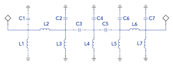
Figure 1 Simplified bandpass filter schematic.
Finally, the Modelithics COMPLETE+3D Library also includes what are known as 3D Brick Models™ for multi-layer ceramic capacitors (MLCCs).3 A 3D Brick Model is a simplified approximation of a capacitor’s physical geometry. However, these models alone do not account for internal device parasitics. Therefore, when using 3D Brick Models, the complete simulation process involves first performing a 3D EM simulation that includes all 3D Brick Models along with all 3D Geometry Models, if the design also includes 3D Geometry Models. This 3D EM simulation captures any coupling interactions that may exist between components. The next step is to perform a 3D co-simulation in a circuit schematic. This 3D co-simulation incorporates the 3D EM simulation data and combines it with the Microwave Global Model(s) for the corresponding capacitor(s) to allow for a complete 3D EM simulation.
Case Study 1: Filter Without Component Spacing Constraints
For the following analysis, lumped-element bandpass filter designs will be examined. The topology used for the filter designs shown here is known as the equal shunt legs topology. This topology is available as a selection in Ansys NuHertz® FilterSolutions (ANFS), which is a tool that enables users to synthesize various types of filters.4 In the case of lumped-element filters, FilterSolutions lets users choose from different topologies, including classical, equal inductors, equal shunt legs, high/lowpass and others.
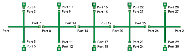
Figure 2 Bandpass filter layout where components have ample spacing.
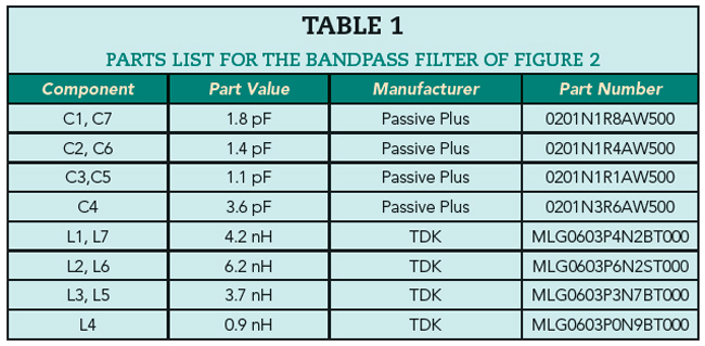
Figure 1 shows a simplified schematic of the filters that will be presented in this case study. The first example considers the case where there is a considerable amount of space between components. Figure 2 shows the layout of the filter with a total length of about 0.929 in. Note that the substrate used is 0.004 in. thick Rogers RO4350B material. The TDK MLG0603P series and the Passive Plus 0201N series, both of which come in a 0201 size, are used for all inductors and capacitors, respectively. Modelithics offers Microwave Global Models for both part series. Finally, Table 1 lists the values of all the inductors and capacitors. For this example, the targeted center frequency is about 1.5 GHz.
The analysis begins by performing a planar EM/circuit co-simulation using Ansys’ 2.5D Method of Moments (MoM) EM solver to simulate the layout shown in Figure 2. A schematic must then be created that includes the planar EM data properly connected to the Microwave Global Models for the MLG0603P inductors and 0201N capacitors. This schematic is shown in Figure 3. Simulating this schematic produces the final planar EM/circuit co-simulation results.
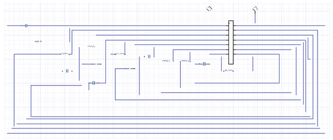
Figure 3 Filter layout planar EM data connected to the Microwave Global Models.
Having discussed the planar EM/circuit co-simulation method, the focus turns to the 3D EM simulation. The planar EM/circuit co-simulation schematic shown in Figure 3 includes Microwave Global Models for the TDK MLG0603P inductors and Passive Plus 0201N capacitors. For the TDK MLG0603P inductor series, Modelithics also offers 3D Geometry Models for inductors ranging from 0.6 to 120 nH. Modelithics also offers a 3D Brick Model for the Passive Plus 0201N capacitor series. Figure 4 shows the bandpass filter of Figure 2, populated with the components of Table 1 in Ansys HFSS with 3D Geometry Models for the TDK inductors and 3D Brick Models for the Passive Plus capacitors.
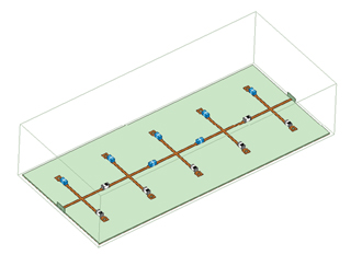
Figure 4 HFSS bandpass filter design with 3D Geometry Models and 3D Brick Models.
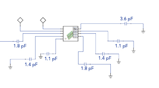
Figure 5 Schematic used for the 3D co-simulation of the bandpass filter.
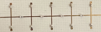
Figure 6 One of the (compact) bandpass filters that was built and measured.
Now, a complete 3D EM simulation is possible by first completing a 3D EM simulation in HFSS of the design shown in Figure 4. The next step is to perform a 3D co-simulation that includes the data from the 3D EM simulation properly connected to the Microwave Global Models for the capacitors. The schematic for this model is shown in Figure 5. It includes the 3D EM simulation data, as the center element, connected to the Microwave Global Models for the capacitors. Simulating this schematic produces the final 3D EM simulation results.