
Data compression is another reason for using in-flight processing. While it may be feasible to capture all the data from a flight, transferring that data to a host platform may require considerable time to facilitate post-processing. Instead, a hybrid approach can be used that captures a subset of full-bandwidth data to allow measurement verification, while abstract measurements like channel RSSI, along with pulse rise and fall times can be recorded for the full measurement sequence.
Level Adaption
Signal level optimization is an additional challenge that is normally accounted for by a technician in a controlled measurement environment. Signal capture platforms have a finite, constrained dynamic range. Most SCR platforms provide programmable signal path gain/attenuation to optimize the available dynamic range for the best signal fidelity for the measurement being made. Utilizing dynamic adaption managed during collection by flight software ensures that signal quality is maximized while trading off against capture performance. A versatile approach allows different techniques to be chosen for different measurement tasks to allow exploitation of this trade-off. These techniques include one-off initial calibration, adaptive/tracking or continuous recalibration for rapidly changing or intermittent signals.
Report Generation
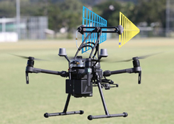
Figure 2 Example drone platform.
Accurate, position-correlated measurement is essential, but it is not sufficient to produce an effective measurement platform. A clear advantage of the headless programmable SCR approach is that all the measurement information is directly available on a general-purpose computing platform where it may be rapidly processed into relevant information for the user. Such processing is even possible during flight, utilizing a telemetry link to deliver early reporting. This reporting demonstrates that the measurement mission is proceeding as intended and it allows real-time operator decisions to optimize the use of flight time. Once a drone has landed, all the data can be rapidly downloaded to a host, facilitating complete report generation. This method realizes an integrated, high-quality, system-measurement solution that does not require a high degree of operator expertise.
CASE STUDY: IN-SITU BROADCAST ANTENNA MEASUREMENT
The ability to measure systems in-situ in normal operation and obtain extensive, accurate diagnostic data at a low cost enables system qualification at installation and proactive ongoing maintenance. This case study utilized a drone platform with radio measurement payload and test antennas, like that shown in Figure 2.
Measurement Setup
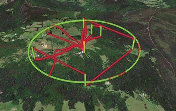
Figure 3 Measurement flight path.
To examine the target broadcast system antenna, a standard flight plan4 was designed to ensure adequate coverage of the expected antenna pattern at the anticipated output power level. Note that in a measurement scenario, a significant amount of calibrated attenuation may need to be added to the signal path from the measurement antenna to ensure the maximum input power of the SCR is not exceeded. Before launch, a suitable test antenna configuration is selected and connected to the in-flight measurement SCR. The antenna and cable setups are calibrated before deployment and on an ongoing basis. The drone platform is then programmed for the required flight plan and the telemetry link from the drone SCR measurement platform is confirmed to be operational. The measurement flight path, showing data collection segments in green and intervening drone transit paths in red, overlayed on a perspective image of the test location is shown in Figure 3.
The flight plan consists of a series of vertical climb/descent sections used to determine the elevation of the main beam of the antenna at a suitable measurement distance. These are then followed by a 360-degree orbital sweep on the measured elevation of the antenna main beam at this radius. During this capture, received signal power is integrated over the bandwidth of one of the active antenna broadcast channels. Note that multiple channels can be measured within a single flight, if required.
Results
This section shows the results from the measurement flight path. Figure 4 shows the elevation pattern for an antenna determined by a vertical scan at the center of the discovered main beam. Figure 5 shows the telemetry link that allows real-time display of collected data to validate the in-flight decision-making to optimize collection time.
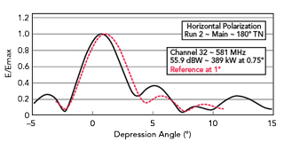
Figure 4 Measured elevation pattern.
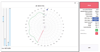
Figure 5 Telemetry link to optimize data collection time.
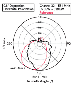
Figure 6 Polar plot of signal strength from a 360-degree orbital sweep on antenna main beam.
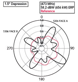
Figure 7 Manufacturing errors impact omnidirectional radiation pattern.
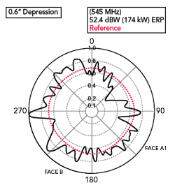
Figure 8 Complex structural interference impacts omnidirectional radiation pattern.
Figure 6 shows the measured antenna output as a solid line, versus the designed pattern shown in the dashed line. It is clear from this measurement that the antenna output is close to what is expected, but the antenna directional output is approximately 30 degrees off the designed azimuth. This error led to a violation of the broadcast license by the operator and poor system performance in the desired reception area.
Other issues can be identified from similar measurements. Figure 7 illustrates sweep results identifying manufacturing defects and Figure 8 illustrates the effects of complex structural interference with the designed antenna output profile.
Direct measurement of deployed and active antenna systems delivers valuable engineering data. The cost-effectiveness and speed with which standardized drone-based measurements can be performed transform this type of measurement from a reactive diagnostic tool to an installation and proactive maintenance tool for system designers and installers.
FUTURE DIRECTIONS
First-generation systems have provided the ability to measure signal strength in space and provide useful data on fixed antenna systems for broadcast-type applications. This covers a wide application space in terrestrial broadcast, cellular and public safety markets. These systems have largely relied on spectral-type measurements and straightforward signal strength determinations from one or more drone-mounted antennas.
Second-generation systems are integrating more sophisticated abilities to process time-domain signals enabling the evaluation of, for example, pulsed radar systems. The addition of more advanced demodulation software on the flight platform enables deeper characterization of signals. These characterizations include things like the complex impacts of multi-path, fading and signal distortion.
Additional opportunities will arise in applications that value the ability to obtain high-quality, spatially accurate measurements at a low cost. These applications may include aviation navigation aids such as Localizer/Glideslope and VOR. For these applications, traditional measurement and characterization approaches are highly time-consuming and expensive.
CONCLUSION
Modern drone platforms combined with evolving high performance programmable receivers combine to open a new range of approaches to antenna systems measurement. The exploitation of this approach is in its infancy as a complement to traditional measurement and system diagnostic techniques. It is exciting to be at the forefront of this innovative approach and to participate in a revolution in radio systems measurement. For the future of radio systems measurement, the sky truly is the limit.
References
- J. F. Aubin. “A Brief Tutorial on Antenna Measurements,” Microwave Journal, Vol. 48, No. 8, August 2005.
- D. Campbell et al., “Simulating Antenna Measurements in an Anechoic Chamber,”Microwave Journal, Vol. 57, No. 5, July 2014.
- H. L. Bertoni, “Radio Propagation for Modern Wireless Systems,” Pearson Education 1999.
- “Airborne Verification of Antenna Patterns of Broadcasting Stations,” ITU-R SM.2056-1, 2014.
- “Freefly Systems Astro RTK,” Web: https://freeflysystems.com/astro.
- “DJI Matrice 300 RTK,” Web: https://enterprise.dji.com/matrice-300.
- “Acecore Zoe,” Web: https://acecoretechnologies.com/zoe/.
- “Aeronavics Navi,” Web: https://aeronavics.com/models-of-drones/navi/.
- “Signal Hound Spectrum Analyzers,” Web: https://signalhound.com/.
- “ThinkRF R5750 real-time spectrum analyzer,” Web: https://thinkrf.com/products/Real-time-Spectrum-Analyzers/r5750-real-time-spectrum-analyzers.
- “Harogic Spectrum Analyzers,” Web: https://harogic.eu/.
- “VITA Radio Link Layer Protocol (VRL) Standard,” VITA 49.1, VMWBUS International Trade Association (VITA), 15th Edition, 2021.