
A miniaturized broadband 4×4 multiple-input multiple-output (MIMO) circular quad antenna module that can be mounted on a metal surface covers the 5G band N77 (3.3 to 4.2 GHz) and is suitable for 5G terminals. It has a radius of 22 mm and a height of 2.4 mm. Isolation between elements is greater than 10 dB and the radiation efficiency is 38 to 68 percent.
In the 4G era, smart terminal antennas were typically integrated into a metal structure.1-3 For 5G, smart devices the trend is toward miniaturization. For a planar antenna, size and profile determine its performance, including bandwidth. In addition to increasing its profile and area, there are several ways to increase its bandwidth with stacked patches.
The first is to use magnetic coupling4-6 by combining the main patch and parasitic patches with shorting pins.4-6 Similarly, bandwidth can be increased by grooving in primary and parasitic patches to achieve the fusion of different modes. A coupling feed7-9 is another effective method, which couples the gap to an upper patch to increase an antenna’s bandwidth. L-type probe feeds are often used as well to increase bandwidth.10-13 The vertical part of the L-type probe generates inductive reactance, while the horizontal part generates capacitance with the patch and the ground plane; these reactances cancel each other to produce a wide frequency band.
Liang et al.14 adapted a method of combining multiple types of stacked patches to realize broadband performance. Bandwidth is also achieved by combining high-order modes and low-order modes by increasing the resonant frequencies of the low-order modes and decreasing the resonant frequencies of high-order modes with shorting pins or etching slots vertical to the current path.15-17
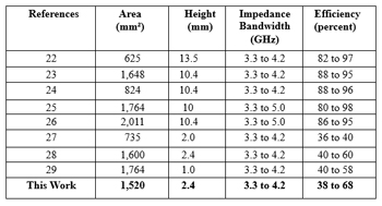 TABLE I - COMPARISON WITH OTHER WORK
Employing multiple antennas (i.e. MIMO) to emit and receive signals18-21 is an efficient use of space. See Table I, which compares the design described in this article with other reported work. In the work of Wong et al.23, 24 a broadband three antenna module uses three different senses of polarization with an angle between two adjacent antennas of 60 degrees in a height of 11.7 mm and an area of 625.27 mm2. In another example, a square four-antenna module with a height of 10 mm and an area of 1,764 mm2 covers the N77 and N78 frequency bands.25 Another approach employs an annual ring structure with a height of 10.4 mm in an area of 2,011 mm2.26 With the size of intelligent terminal equipment becoming miniaturized, however, space is becoming so constrained that antennas with a profile of 10 mm are no longer suitable for many applications.
A low-profile four-antenna module covering the 5G N77 band has a height of 2 mm and a diameter of only 30.8 mm.27 A four-antenna module with a height of 2.4 mm and an area of 1600 mm realizes wideband performance by adding a shorting pin to form TM1,1 and TM1/2,1/2 modes.28 Another four-antenna module has open slots that are connected to each other. Its height is only 1 mm.29
The antenna described in this work covers the 5G N77 band (3.3 to 4.2 GHz) with a low-profile structure suitable for mounting on metallic surfaces. Two resonant modes are excited by loading a shorting pin to achieve wide bandwidth.
ANTENNA DESIGN AND ANALYSIS
Antenna Structure
Figure 1 shows the exploded view, plan view and side view of the circular antenna. The antenna height is 2.4 mm and the size of the ground plane is 60 x 60 mm2. Since the length of the ground plane is well over half a wavelength at the antenna's lowest frequency (3.3 GHz), it does not affect antenna performance. This allows the antenna to be used on any type of metal platform.
The antenna has three parts: the bottom basal plate, the top basal plate and the air layer. The substrate material is FR4 (εr = 4.4, tanδ = 0.02), fed by a microstrip line. Four equally spaced shorting pins are placed in the middle of each quarter circle to connect the antenna to the ground plane. In practice, all shorting pins are connected by red copper wires. Dimensions of the antenna parameters shown in Figure 1 (in mm) are R1 = 4.5, R2 = 0.3, R3 = 0.5, L = 60, L1 = 18.7, L2 = 5.4, W1 = 1.6, W2 = 1, S = 3.2, H1 = 0.5, H2 = 0.5 and H3 = 2.
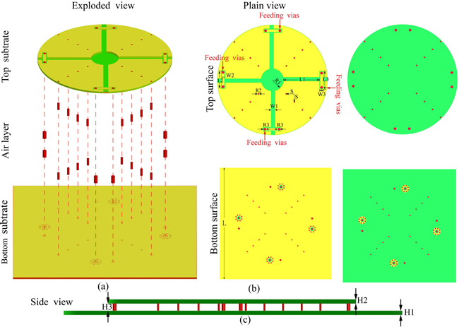
Figure 1 Low-profile wideband circle patch MIMO antenna: exploded view (a) plan view top surface (b), plan view bottom surface (c) and side view (d).
Design Evolution
Each port of the antenna forms two resonant modes. Cross slots with widths of 1.6 mm are etched in the circular patch to form a quarter circular resonant TM1,1 mode for each antenna port. This is the basic mode produced in the quarter-round patch. Shorting pins are then installed on a line bisecting each quarter circle. The shorting pins are located at the center of the quarter circle, which is also the location of the TM1,1 mode null, thus exciting the TM1/2,1 anti-resonant mode. Since the paths of the two resonant edges do not differ by much, the two operating modes are excited at frequencies close to each other, creating a broad operating frequency band.
In addition, the feed employs microstrip line coupling. When using a coaxial feed, the probes create a strong inductive impedance on the antenna, and the use of slot coupling can effectively mitigate the inductive impedance from the probes. This is also an efficient way to adjust impedance matching.
Figure 2a shows Case A with only cross slots, Figure 2b shows Case B with only shorting pins, Figure 2c shows Case C with both cross slots and shorting pins, which is the final structure of this design. Figure 2d indicates the resonant regions of the patch.
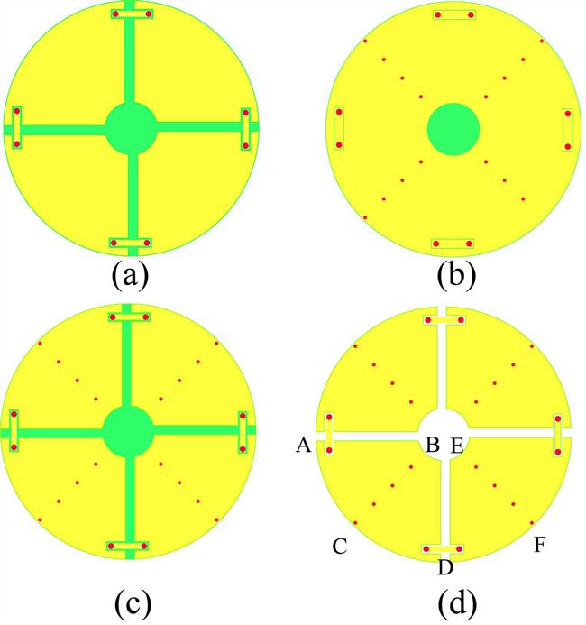
Figure 2 Case A – cross-slotted antenna (a) Case B – antenna with shorting pins (b), Case C – antenna with both cross slots and shorting pins (c), resonant patch regions (d).
Since the antennas are arranged in order of selection, the results for port 1 and Ports 2-4 are the same, so only the results for port 1 (i.e. Antenna 1) are given. Figure 3a shows S-parameters for Case A. The shaded area is the frequency range required for this design (3.3 to 4.2 GHz). Its center frequency is 4.064 GHz and it has a – 6 dB impedance bandwidth of 300 MHz, from 3.9 to 4.2 GHz.