

As we advance towards the era of 6G and explore the potential of non-terrestrial networks (NTNs), the role of power amplifiers (PAs) in RF communication systems becomes increasingly important. Traditional PA testing methodologies are now being challenged by the complexities of emerging technologies. An emerging approach to PA testing is wideband active load-pull (WALP). This article explores how WALP offers enhanced accuracy and capability while addressing the demands of PA design and optimization in the dynamic landscape of 5G, 6G and NTN communication systems.
ASSESSING PA PERFORMANCE
After the detailed modeling, simulation and design of the transistor, along with designing the primary matching network for fundamental and harmonics frequencies, PA modules are fabricated and prepared for rigorous testing. Ensuring that PAs meet essential performance, efficiency and reliability specifications is a pivotal stage in PA development and manufacturing for communication systems. This testing involves several steps to assess PA performance:
Design verification under 50 Ω conditions: The initial stage involves testing PAs against predefined design targets, measuring various parameters such as frequency response, gain, output power, nonlinearity and efficiency. This testing is measured typically under 50 Ω load conditions, for both CW and modulated stimulus signals.
Performance assessment under various load conditions: Traditional methods including passive, active and hybrid load-pull were predominantly used with a CW stimulus. For a modulated stimulus, passive load-pull solutions are often used, but these solutions are faced with the challenge of controlling the load to the specified conditions across the frequency band. This is particularly true for wide frequency, bandwidth-modulated signals. The active load-pull method addresses this challenge by allowing for precise control of load conditions across a wide frequency range.
Ruggedness testing: Focusing on the PA’s durability and reliability, robustness testing subjects the PA to extreme conditions, such as high power levels and mismatched loads. This is done to evaluate the ability of the PA to operate without failure or degradation over time. This step is crucial in ensuring the longevity and robustness of the PA in actual applications.
Comprehensive PA testing is essential to ensuring that PAs meet the stringent demands of modern RF communication systems. This is particularly true since PAs are deployed in a variety of field conditions. As communication technologies evolve to include phased array or MIMO technologies, the importance of accurate and thorough PA testing under various load conditions becomes increasingly important.
VNA-BASED WALP OVERVIEW
In response to these evolving PA test challenges, vector network analyzer (VNA)-based WALP solutions have been developed. These approaches are designed to address the limitations of traditional PA testing methods, particularly in the context of wideband modulated signal conditions. The VNA-based WALP solution stands out for its ability to provide accurate and comprehensive insights into PA performance across a wide range of load conditions. This is especially crucial in the 5G era and beyond, where PAs must operate linearly and efficiently over broader frequency ranges and under various driving conditions.
Hardware configuration: The hardware block diagram of the VNA-based WALP system is shown in Figure 1. The device under test (DUT) is stimulated by a dual-channel RF vector signal generator. Phase coherence between the two channels is required so that the stimulus at the input of the DUT is synchronized to the stimulus at the DUT output. Vector and power calibration at the DUT connectorized reference plane is used so the four traveling voltage waves can be accurately captured by the VNA.
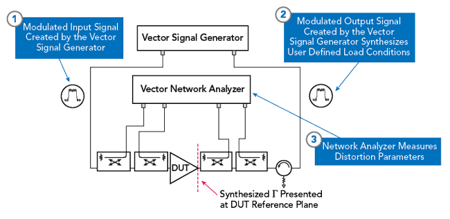
Figure 1 Hardware block diagram of VNA-based WALP system.
Software tools: To specify target load conditions over the measurement bandwidth and comprehensively analyze nonlinear distortion characteristics, software tools are required for the VNA-based WALP. Additionally, the advanced calibration techniques and algorithms of the VNA are essential to capture calibrated signals at the reference plane.
WIDEBAND LOAD-PULL METHODOLOGIES: PASSIVE VS. ACTIVE
Unlike CW signals with a single tone in the frequency domain, modulated signals are represented by a multi-tone spectrum with a given bandwidth in the frequency domain. At the output of the DUT, a variable, controlled load condition is desired since the PA can experience changes to the load condition depending on the operating conditions. For example, PAs that are used in phased array antennas will experience a change in the load condition as the beam angle changes. Passive and active load-pull techniques have different approaches to present a desired gamma (Γ) at the DUT output.
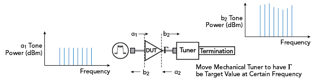
Figure 2 Passive load-pull setup.
Passive Load-Pull
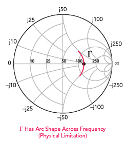
Figure 3 Gamma trajectory of passive load-pull for a modulated signal.
Passive tuners control the impedance over a given frequency range using a low-loss transmission line with an insertable electronically-controlled reflective probe. The probe interferes with the electrical field and generates a reflection coefficient with a magnitude and a phase angle. These tuners can be geared toward the fundamental or harmonic signals and they are limited to generating gammas that are less than one. Although passive tuners can handle high power and help simplify the test setup, there are drawbacks to using passive tuners in wideband measurements. Any loss in the transmission line and test set will further constrain the maximum achievable gamma when using a passive tuner. This will limit the magnitude of the gamma values that can be presented to the DUT. Additionally, tuners used for wideband or high frequency load-pull measurements can introduce significant errors due to trajectory deviations of the gamma over the frequency band.
Figure 2 shows a typical passive tuner setup for load-pull measurements. The measurement results from this typical setup are shown in Figure 3. The modulated input signal results in a gamma that has an arc shape as shown in Figure 3. This is due to the phase of the reflection changing with frequency and this presents a physical limitation. The frequency-dependent phase variation of the reflection coefficient is due to the electrical delay of the cables and tuner and could be different from the user-specified gamma. The targeted gamma is 0.4, zero degrees for the specified center frequency and is represented as the dot on the Smith Chart.
Active Load-Pull
Active load-pull techniques inject an incident wave into the output of the DUT to synthesize a gamma condition. There are two conceptually different methods in active load-pull; closed-loop and open-loop. Closed-loop techniques couple the DUT-generated b2 signal from the signal path where the amplitude and phase can be adjusted and injected into the output of the DUT as the α2 signal. Open-loop techniques do not reuse DUT-generated waves but instead use a second signal source to inject power on the output side of the DUT to synthesize the gamma condition at the frequencies of interest. Figure 4 shows a simplified block diagram of an open-loop configuration.
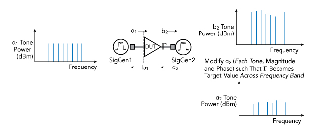
Figure 4 Open-loop active load-pull block diagram.
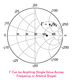
Figure 5 Example gamma controlled by WALP across the frequency range.
One method of open-loop active load-pull uses an algorithm that minimizes the complex error between the measured and targeted reflection coefficient for a given modulated input signal. The first step is to upload IQ samples to SigGen1, shown in Figure 4, to generate the input wave α1. The output wave, b2, is measured and the required IQ samples for α2 are computed to achieve the desired gamma. The IQ samples are uploaded to SigGen2, shown in Figure 4, and the actual α2 is evaluated. This process is iteratively repeated until the desired gamma is achieved at the DUT output reference plane.
This method of active load-pull enables gamma values that can be arbitrarily defined for the modulated signal bandwidth. In Figure 5, gamma is targeted to have a single-phase value across the frequency range. However, gamma, defined as α2/b2, can be a single value across a frequency range or any arbitrary shape.