
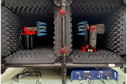
Many factors influence measurement accuracy for antenna patterns and radiated power levels in over-the-air (OTA) test systems. A primary consideration is the distance between the measurement probe and the radiating device or antenna under test (AUT). In typical measurement systems, each device should be outside the near-field and Fresnel regions of the other device. Equivalently, the probe and the AUT should be within each other’s far-zone regions. The distance to this region is often estimated as 2D2/λ where D is the diameter or length of the antenna and λ is the operating wavelength. In a compact range, where a parabolic reflector projects a plane wave onto the AUT, the separation distance can be much smaller.
In directional antennas, the effective aperture area, Ae, is computed as λ2G/4π where G is the antenna gain. If a directional antenna’s effective aperture area is approximated as a circle with diameter D, the far-zone distance is estimated as 2λG/π, where G is the antenna gain expressed as a power ratio. For D-Band measurements, the far-zone distance from an antenna with 20 dBi gain is approximately 17 cm at 110 GHz and 11 cm at 170 GHz. If the measurement probe and the AUT have similar levels of gain, the separation distance should be at least twice these values. A test system with a 77 cm separation between the probe and the AUT easily meets the spacing requirements typically encountered for D-Band measurements.
New developments in small-profile transmit/receive frequency extenders for vector network analyzers (VNAs) are complemented by a wider range of choices for measurement enclosures, VNAs, robotic positioning systems and phase-stable coaxial cables. When evaluating any OTA measurement system, start by comparing the far-zone distances required for accurate test results to the measurement distances provided.
Eravant
Torrance, Calif.
www.eravant.com