

Aerospace and defense (A&D) applications present some of the harshest environmental conditions for high performance electronic technologies. The mission-critical RF systems in these applications serve as the backbone for a range of vital technologies, including satellite communication, electronic warfare (EW), intelligence, missile guidance, radar and hypersonic systems. An ongoing evolution of hardware components and interconnection solutions is needed to meet the rigorous demands imposed by cutting-edge technologies and to ensure flawless operation in harsh and variable environments.
The effectiveness of RF systems fundamentally depends on the integrity of those hardware components and how they interact. While some installations can tolerate standard products, others necessitate custom-designed solutions tailored to unique specifications. In the ever-changing landscape of the A&D industries, there is a growing demand for high performance connectors that can withstand harsh conditions, severe vibrations and extreme temperatures while still delivering consistent performance.
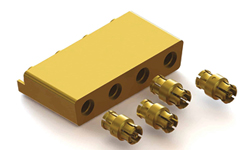
Figure 1 Representative assembly interface with SMP connectors.
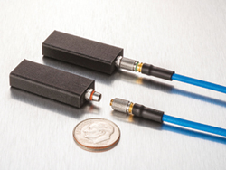
Figure 2 TLMP connectors.
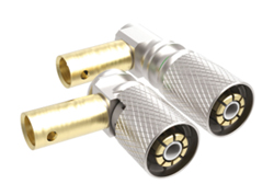
Figure 3 TLMP right-angle connectors.
In many applications, legacy connector designs, such as the sub-miniature push-on (SMP) shown in Figure 1 or sub-miniature push-on micro (SMPM) are no longer sufficient to meet the requirements of evolving system technology. They are susceptible to issues like electromagnetic interference (EMI) and electromagnetic compatibility (EMC), lack environmental sealing and have the potential to disengage in response to the impact of a hard landing. These issues have spurred new RF interconnect designs to address these challenges more effectively. Among these, locking miniature push-on and locking miniature blind mate connectors have emerged as the new industry standard, specifically tailored to rectify the shortcomings of legacy technologies.
These advancements in connector designs are in response to the development of a new generation of A&D applications that continually push the boundaries of power handling and performance. These new connector types are engineered for high peak power conditions at high altitudes. These advancements will be crucial for the next wave of military communication systems designed for harsh environments.
This article will detail how these developments are enabling reliable high performance in demanding, dynamic and harsh environments. It will explore the RF interconnect designs required to handle these challenges. Additionally, it will offer insights into emerging applications that demand multifaceted connectivity solutions.
THE NEW INDUSTRY STANDARD
Evidence of the evolution of interconnect designs can be seen in the increasing popularity of smaller-sized, O-ring sealed connector solutions that surpass their SMP/SMPM predecessors. These new solutions offer enhanced shielding, along with better environmental protection and mechanical retention. These new design efforts have resulted in the introduction of the Times locking miniature push-on (TLMP™) and Times locking miniature blind mate (TLMB™) connector families, which are specifically designed to address EMI concerns for applications that require environmentally sealed and shielded connectors. The TLMP connector type also addresses high vibration environments such as a carrier landing, weapons launch or similar harsh platform environments. Figure 2 shows cables terminated with the TLMP connectors. Figure 3 shows a right-angle connector using the TLMP design concept.
This connector class maintains the small form factor dimensions of SMPs while improving shielding and environmental and power handling capabilities over a frequency range from DC to 60 GHz. To minimize signal leakage, the mating component effectively covers the connector’s slots. This construction enables these connectors to reduce EMI and EMC interference as well as liquid and salt ingress. The sealed design also enhances the resilience of the connector to harsh conditions and severe environments. Overlapping insulators eliminate a direct path to the ground from the center conductor to the outer shield, enabling higher voltage functionality.
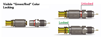
Figure 4 TLMP color-coded locking engagement.
In addition, the connectors incorporate a latching mechanism that improves their mating retention capabilities. This will differentiate these connectors versus threaded body alternatives. A verification feature with red (unlocked) and green (locked) color coding provides visual confirmation that the connectors are fully mated and locked. The locking blind mate version is equipped with an additional outer sleeve to increase the protection of the tines in blind mate applications. This color-coded locking mechanism is shown in Figure 4.
THE NEXT LEAP FORWARD
As harsh environment applications become more widespread, this increases the need for high-density, high-power connector solutions. As a result, locking miniature push-on and blind mate connectors are evolving to accommodate higher CW power and frequencies above 18 GHz. These new connector types become important to the reliability of communication systems. The connectors are well-suited for a wide range of applications, including densely-packed signal intelligence, electronics intelligence and EW systems.

Figure 5 TLC connector design.
The Times locking connector (TLC) is an example of this next leap forward. The connector was engineered with a 0.040 inch line size design and was built to handle higher transmit powers commonly found in aircraft systems. This connector utilizes a Polytetrafluoroethylen (PTFE) blend with ceramic filler dielectric instead of regular PTFE to improve the thermal dissipation characteristics. These new dielectrics possess 8x the thermal dissipation capacity of PTFE, giving this connector type better heat dissipation properties. This design change helps this connector type address high CW power applications at higher altitudes. This connector maintains its performance characteristics up to 23 GHz. An example of the TLC family of connectors is shown in Figure 5.
There are cases where the TLC connector may be too large. To address these situations, the company has developed the Times locking push-on connector (TLPC). This connector handles high power levels in a considerably smaller form factor. The TLPC features a 0.030 inch line size and is available in multiple versions, including card edge and various edge launch configurations. The TLPC family is designed for many integration scenarios, whether that is threading the connector through the wall of a box or soldering it to the ground plane and the center pin or trace on the board. The design of the connector makes it suited for applications up to 32 GHz.
Sophisticated defense systems will incorporate numerous sub-system components and may include a dense collection of antennas. This increases the demand for cables and connectors, along with increasing the density of these components. The connector designs that have been described can be incorporated into multiport versions, eliminating conventional coupling nut schemes. This improves space utilization and operational efficiency. In this multiport configuration, the interfaces are integrated into male and female shells, effectively serving as bulkhead disconnects to enable higher interface densities.
APPLICATION EXAMPLES
The blend of advanced signal processing and sensing capabilities, combined with integrated hardware, helps unlock critical insights from very large data sets. This empowers military aircraft with more accurate and comprehensive systems and enhances functionality and safety. As this innovation accelerates, connectors must rise to the challenge of handling higher frequencies, faster data transmission speeds and increased power demands while being subjected to the same or harsher operating environments than previous generations of connectors.
As defense systems have evolved, they have moved higher in frequency in search of more bandwidth. Many current systems operate in the 23 to 60 GHz frequency range and some systems go higher in frequency, enabling faster target detection and more precise tracking. The increasing channel bandwidth enables faster data transmission rates for incoming and processed signals. Onboard processors quickly filter and analyze this data to identify threats and facilitate rapid responses. Printed circuit boards (PCBs) are pivotal in supporting rapid connections between components or other PCBs in this sophisticated network. The design enhancements in the TLMP™-, TLMB™-, TLP- and TLC-series connectors target the emerging requirements of these applications to minimize signal loss and interference.
As airborne applications push the boundaries of speed and altitude, connectors must be able to handle elevated power levels while maintaining an appropriate balance between size, weight and power performance. As an example of these considerations, if an airborne system includes an active electronically steered array, the phased array radar will likely contain many small radiating elements to form and steer the radar beams. In this case, the radar processor box will orchestrate a complex symphony of RF and digital technologies, along with many radiating elements. The TLP- and TLC-series are engineered to support the inherent challenges in this demanding application. The speed barrier will be pushed even further by applications like hypersonic weapons. Connector designs incorporating materials like boron nitride dielectrics that can withstand the extreme temperatures caused by hypersonic speeds are emerging.
NEW REQUIREMENTS DEMAND COLLABORATIVE PARTNERSHIPS
New designs often require the connectors to maintain the highest performance in the harshest environments. Collaborating with experienced suppliers that have deep expertise and a trusted heritage of engineering development in mission-critical applications is an important consideration in the specification and design process. The chosen partner must thoroughly understand material technologies and possess in-depth knowledge of the specific applications, encompassing the aircraft, environmental factors and underlying physics. Manufacturers are finding that they need to adopt this holistic approach to ensure that they develop optimal solutions.
This holistic approach is increasingly extending to incorporate the RF supplier. Given the highly complex nature of A&D systems, which rarely use standard solutions, the technical team must ask the right questions to understand the unique requirements of an interconnection application. A collaborative effort is proving instrumental in creating solutions that offer superior electrical, mechanical and environmental performance.
A&D system designers and integrators should consider the following when choosing an RF interconnect supplier:
Heritage and qualifications: Many RF suppliers offer a wide variety of standard capabilities, but A&D requirements are unique. Search for a partner with a wealth of relevant experience to help develop RF systems that can withstand the rigors of A&D environments, deliver reliable performance and adhere to stringent safety requirements.
Dedicated technical experts: Avoid partnering with a supplier focused on mass-market products. The first approach from these suppliers may be to offer the same product they sell to everyone else. Always request to engage with their technical experts. Additionally, the supplier should assist you in understanding the electrical and mechanical trade-offs specific to your application.
A large breadth of products: A supplier with an extensive product portfolio is better positioned to offer the ideal solution for a specific application. When selecting the best solution, it is advantageous to have a variety of options. These may include different cable constructions, various connector designs that range from low power to high power and a diverse set of assembly techniques that are all available from a single supplier.
Defense applications will likely mandate the use of acceptable materials and MIL-SPEC-compliant processes and requirements. Being able to meet these stringent standards is essential for the environments and conditions associated with every defense application and environment. However, a universal standard for material selection and design of a consistently reliable RF solution does not exist. Instead, the expertise and comprehensive range of product options from a supplier become invaluable tools to ensure an optimal solution. Some of the factors to consider:
Manufacturing execution: In an ideal scenario, the RF supplier possesses the full spectrum of technology and products that are required and understands how to integrate them into a finished product. It then becomes important to evaluate the manufacturing operations. Does the company have robust facilities and well-defined processes that ensure seamless execution? Cleanroom manufacturing capabilities are essential, as well as traceability in managing all the parts that go into complicated, multifunction assemblies. It is also important to know which quality standards the supplier uses, as well as any extended services that they offer.
Agility: Finally, it is important to select an RF partner that is operationally and financially strong enough to deliver short-term results, while also being able to withstand turbulence in markets.
LOOKING FORWARD
To adapt to the evolving demands of A&D systems that operate in harsh environments and demand high performance, connector designs are also evolving. These new designs from Times Microwave offer substantial reductions in physical footprint and they are available in single-mount or multiport versions that support the higher connection densities and power thresholds of emerging applications. These designs must also solve the EMI and environmental issues that challenged earlier generations of RF connectors while ushering in a new era of performance in the most demanding, variable and extremely harsh environments. The need to build high performance end products for emerging applications is also fostering an environment where collaborating with an experienced partner with deep engineering expertise and a trusted legacy of development in mission-critical industries has become even more important to ensure the continued superiority of A&D systems.