

There are some catalog surface-mount technology (SMT) filters available for high volume applications, mostly in the industrial, scientific and medical, cellphone and Wi-Fi bands. Most of these filters use proprietary LTCC, SAW and BAW technologies. For other applications, there is a need for quick, custom filter designs that can be realized using standard SMT capacitors and inductors. However, there are some interesting choices to be made regarding filter topology that can have a significant impact on filter performance. The Modelithics CLR Library1 and Cadence AWR Microwave Office software2 are the right tools to explore these issues and achieve successful designs. The DGS Associates equal ripple filter optimizer, EQR_OPT_MWO, is also a key tool in our design flows.3
CONVENTIONAL TOP-COUPLED TOPOLOGY
To design a lumped element bandpass filter, it is tempting to start with the conventional top-coupled shunt resonator topology that is found in many textbooks. This topology is shown in Figure 1 (a). The top coupling in this approach can be inductive or capacitive. In higher-order filters, a mixture of the two couplings can be found that results in fairly symmetric stopbands. For physically symmetric filters, the DGS Associates optimizer will find an equal ripple response with or without loss. The simulated frequency response of this topology is shown in Figure 1 (b).
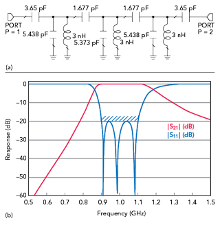
Figure 1 (a) Top C-coupled bandpass filter schematic. (b) Top C-coupled bandpass filter frequency response.
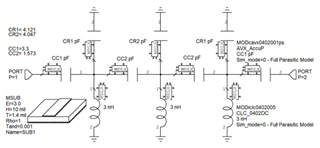
Figure 2 Top C-coupled bandpass realized with SMT components.
The schematic of Figure 1 (a) is translated into 0402 SMT components as shown in Figure 2. The first conclusion is that the element values have shifted significantly compared to the ideal prototype. This analysis ignores microstrip junctions and vias for now but it includes pad stacks. Figure 3 shows the simulated results of the filter topology from Figure 2 and there is a significant spurious response in the upper stopband that we assumed was caused by the inductors.
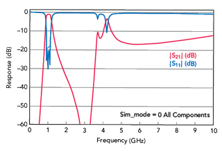
Figure 3 Filter simulation including all parasitics with Sim_mode = 0.
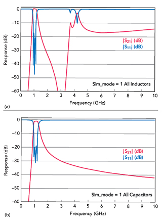
Figure 4 (a) Frequency response with all inductors ideal. (b) Frequency response with all capacitors ideal.
The Sim_mode feature in the Modelithics library allows users to do some simple experiments by temporarily making the inductors and capacitors ideal. Setting Sim_mode=1 for the inductors makes them ideal and the spurious response hardly changes, as shown in Figure 4 (a), making only the capacitors ideal results in the close-in spurs disappearing as shown in Figure 4 (b). Further testing indicates it is primarily the shunt capacitors that are the problem.
It appears that this is a packaging issue with multilayer SMT capacitors that is not widely understood. It is largely independent of capacitor value, but does improve some as package size shrinks. Even the Accu-P capacitors4 used here, which have a radically different internal structure, have spurious response issues.
MINIMUM-C TOPOLOGY
The so-called Minimum-C topology converts two of the parallel shunt resonators to series resonators and puts them at the input and output of the filter as shown in Figure 5. The spurious response is improved compared to the top C-coupled filter as shown in Figure 6. Because this network lacks the symmetry of the top-coupled topology, the optimization strategy is slightly different. In this case, the Expert Mode in the Modelithics models is used to set equivalent series resistance (ESR) equal to zero. Running the optimizer results in an equal ripple response in the passband. When the converged results are satisfactory, the user can change the ESR setting back to the default.
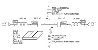
Figure 5 N = 3 Minimum-C topology bandpass filter.
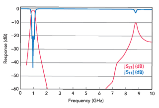
Figure 6 Frequency response with SMT components.
CAUER-CHEBYSHEV ELLIPTIC FUNCTION TOPOLOGY
Adding two more elements results in the N = 3 Cauer-Chebyshev elliptic function topology which is quite efficient for moderate filtering requirements in a very small footprint. This topology is shown in Figure 7. When compared to the Minimum-C topology, the Cauer-Chebyshev elliptic topology has lower insertion loss and steeper rejection in the stopbands, as shown in Figure 8. Considering insertion loss and practical element values, a bandwidth of 15 to 20 percent and minimum rejection of -30 dB in the stopbands seems to be a sweet spot for this topology. These filters have been built with center frequencies from 900 MHz to 6 GHz. This topology can be synthesized using Cadence AWR iFilter as described in Appendix A. Lookup tables can be found in Reference 5.
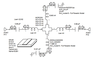
Figure 7 N = 3 Cauer-Chebyshev elliptic function filter with all inductors at the common junction.
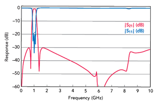
Figure 8 Frequency response of the Figure 7 topology.
When optimizing this topology, either the series capacitors or the series inductors at the input and output are held constant, which sets the filter return loss level. In the shunt arms, one element is held constant in each to set the transmission zero locations. After the optimization converges, each of these fixed elements can be modified to fine-tune the return loss and the zero locations. Because the optimization is so fast and repeatable, this adjustment process goes quite quickly.