

Satellite communication plays a key role in meeting the relentless demand for connectivity in society. Our industry is seeing a game-changing deployment of infrastructure on the ground and in space, driving the need to maximize the use of the finite radio spectrum. The more efficient we are, the more users will benefit.
QuadSAT has developed a technology to ensure efficient and reliable use of the radio spectrum, allowing satellite operators to deliver more services to more customers while maintaining high quality and availability. This development results from a new method of testing and verifying satellite ground station antennas and RF equipment using drones. By pairing a drone-mounted RF payload with unique pre- and post-flight software, ground station and user terminal satellite antennas can be tested throughout their lifecycle.
The technology was initially offered as a service, which made it possible to bring solutions and perform verification missions for satellite companies. This also provided the opportunity to test the capabilities in operational environments, allowing QuadSAT to hone the product, which is now available both as a product to customers with high testing demands or service providers and as a service for those users where that is preferable. The goal of this product evolution is to make testing more accurate, accessible and cost-effective for global users.
DRONE-BASED ANTENNA TESTING
Using drones for antenna testing and measurement introduces new capabilities and removes a large amount of complexity normally associated with this testing. The measurement system can be taken to the site while ensuring a level of accuracy comparable to traditional measurement methods. These tests are fully automated, flexible and location-independent. The system already supports a wide range of measurements critical for ground station equipment, with more features and capabilities in development.
Raster Scans
Measuring the radiation pattern is a fundamental feature of the system and this capability has been used on nearly all our missions. Determining an antenna’s performance requires knowledge of the radiation pattern. Without this knowledge, comparing performance between antennas and identifying issues becomes very difficult.
Raster scans are a way of measuring the radiation diagram on a 3D plane and compared to a single cut it provides much more information about the antenna properties. Their application includes:
- Capturing the radiation diagram of the antenna and painting a clear picture of the main beam and sidelobes
- Determining the state of the antenna performance, i.e., checking for problems with focus, misalignment or manufacturing tolerances
- Measuring and calibrating the pointing mechanism of the antenna
- Tracking changes in the antenna diagram between equipment modifications.
To perform the measurement, the operator plans a flight path for the drone by specifying the width of measurement in azimuth and elevation, as well as the granularity of the measurement lines. The drone flies autonomously on the path and maintains constant pointing and polarization alignment with the antenna under test (AUT). The result is generated by merging the measured amplitude levels with the computed angular position of the drone compared to the AUT. The data points are interpolated and presented in a heatmap or 3D diagram. This process takes around 15 minutes of flight time, with the result generated almost immediately. These results then enable users to:
- Apply contours and determine the 3 dB beamwidth
- Compute beam center
- Verify levels against regulatory masks
- Compare results between measurements
- Extrapolate cuts for regions of interest.
Figure 1 shows an excerpt of the graphical user interface, a representation of the drone flight path, along with a sample output for a representative raster scan for a co-polar and cross-polar measurement. QuadSAT has performed measurements at frequencies from C-Band to Ka-Band for antenna sizes ranging from 40 cm to 17 m and distances from 50 m to 12 km.
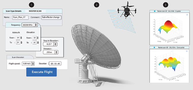
Figure 1 Raster scan process diagram.
Antenna Tracking Verification
Since medium earth orbit (MEO) and low earth orbit (LEO) satellites move relative to Earth, antennas must be able to accurately track the satellite. The rise of new MEO and LEO constellations introduces unknown complexities and being able to quickly evaluate and verify antennas and algorithms can prove to be mission-critical. Identifying potential system issues promptly can help avoid costly delays.
The drone introduces the possibility of simulating satellite passes in real-time, from any direction and at any peak angle. This enables the user to holistically test and verify the tracking and pointing performance of LEO/MEO ground segment antennas, gateways and user terminals. The system can perform make-before-break and handover procedures, along with simulating multiple-beam tracking. It can also simulate real-life scenarios of loss and re-acquisition, launch and early operations or tracking with minimum power levels, sudden changes in frequency, amplitude, modulation type, trajectory, etc. and provide results as well as key performance indicators useful in evaluating the state of the system under test.
To activate this capability, the user locks a precise measurement reference system where the test will be performed. The passes are generated on demand based on peak azimuth and elevation and desired orbital parameters of the satellite. The output, in either TLE or ECEF format, is uploaded into the antenna and the angles and received signal levels are recorded during the pass. A single flight can contain up to four passes and the full-duplex functionality enables the drone to fully simulate a satellite transponder by receiving and storing I/Q data, as well as replaying or transmitting a modulated carrier back to the system under test. The data can be used to perform a calculation of tracking offsets as well as an assessment of the link quality and system reaction in various simulated events. A diagram of this process is shown in Figure 2.
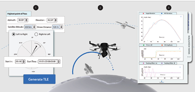
Figure 2 Antenna tracking verification process diagram.
Other Measurements
Besides the measurement techniques described, several other measurements are possible. These include wide radiation cuts, absolute gain, cross-polarization discrimination and axial ratio, as well as environment reflectivity analysis and holistic pointing offset assessment. QuadSAT is constantly upgrading the feature list, working in close cooperation with customers to provide the best solutions.
SUMMARY
QuadSAT has developed this technology to make it cost-effective to test ground station antennas throughout their lifecycle of prototyping, qualification, factory acceptance testing, site acceptance testing, calibration and troubleshooting post-deployment. By expanding the service delivery approach to include licensing partners globally, any user can get antenna measurements cost-effectively and responsively, avoiding months of waiting time.
QuadSAT
Odense N, Denmark
www.quadsat.com