
6G aims to be the first generation of wireless technology to improve the quality of human life by bridging the physical, digital and mechanical worlds. Accomplishing this will mean adding artificial intelligence to networks to make them more efficient and building high fidelity digital twins. It will also require expanding spectrum use and building upon network architectures like non-terrestrial networks and highly virtualized disaggregated networks that began in 5G.
For 6G to meet these goals, the spectrum allotted for wireless communications needs to be used more efficiently and new spectrum needs to be studied. Without expanding into new spectrum bands, it will be impossible to meet the high data throughput needs of applications like immersive telepresence, virtual reality and extended reality.
EXPLORING NEW SPECTRUM FOR 6G HIGH DATA THROUGHPUT RATES
The 220 to 330 GHz sub-THz frequency band can potentially use extremely wide swaths of contiguous spectrum. Although this spectrum could help increase data throughput, there will be significant RF and baseband challenges when using these extreme bandwidths. From an RF perspective, the achievable system performance is uncertain at such high frequencies and with such extreme bandwidths. As bandwidths increase with higher frequencies, the signal-to-noise ratio (SNR) decreases. Channel impairments, along with linear hardware amplitude and phase impairments, become significant compared with narrow bandwidth systems. Robust channel estimation and equalization become increasingly challenging in low SNR environments with significant channel impairments. Waveform quality decreases, limiting or precluding the use of higher-order modulation schemes. Overcoming free space path loss to maintain sufficient SNR for adequate link budget performance requires high gain, high directivity antennas such as phased array antennas or other techniques.
From a baseband perspective, channel estimation and equalization become increasingly complex for robust performance in low SNR scenarios. Receiver baseband algorithm implementations become challenging because of the higher sample rates needed to support extreme RF modulation bandwidths. Baseband resource parallelization increases to support high sample rates, quickly consuming baseband resources. At the same time, more robust and complex algorithms are necessary to perform channel estimation and equalization in low SNR scenarios over extreme bandwidths.
Sub-THz performance in the 220 to 330 GHz frequency band is relatively uncharted territory. There is limited availability of commercial off-the-shelf (COTS) hardware in this frequency band for early measurements. Relatively few publications show system-level RF performance, such as error vector magnitude (EVM) in this frequency band over wide or extreme modulation bandwidths.
This article presents two case studies to provide insight into system performance for the 220 to 330 GHz frequency band:
- Conducted EVM measurements provide insight into understanding what level of EVM performance is achievable over wide bandwidths with low SNR. EVM measurements are performed with up to 30 GHz of occupied bandwidth, which corresponds to a bandwidth where data throughput approaches 100 Gbps for a single stream of data.1 6G applications will involve over-the-air (OTA) transmissions, but first performing conducted EVM measurements yields insights into best-case performance.
- OTA EVM measurements provide insight into understanding what level of OTA EVM performance is achievable over transmission distances. This article looks at a case study using quasioptic techniques for an OTA point-to-point transmission at 285 GHz with 30 GHz occupied bandwidth over a distance of 26.5 ft. (8 m) and discusses key findings.
GAIN INSIGHT WITH CONDUCTED EVM MEASUREMENTS
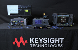
Figure 1 Sub-THz test bed for 220 to 330 GHz.
For this section, the Keysight sub-THz test bed shown in Figure 1 was used to perform conducted EVM measurements with waveguide connected to waveguide.
Test Bed Overview
The M8199A 128 GSa/s four-channel arbitrary waveform generator (AWG) generates wide bandwidth modulated IF signals. The M8199A AWG has an analog 3 dB bandwidth of 65 GHz. A Virginia Diodes Inc. (VDI) compact WR3.4 up-converter (N9029ACST-U03) converts the IF from the M8199A AWG to the desired sub-THz frequency. This up-converter uses a multiplication factor of either 6 or 12 for the local oscillator (LO) frequency (×12 version shown in this picture). An E8257D PSG analog signal generator with option UNY provides a low phase noise LO for the VDI up-converter and down-converter. A VDI-Erickson PM5B power meter with WR3.4 waveguide taper is used for power measurements.
On the receive side, a VDI compact WR3.4 down-converter (N9029ACST-D03) converts the sub-THz frequency to an intermediate frequency (IF), using a multiplication factor of either 6 or 12 for the LO frequency (×12 version shown in this picture). A high performance 110 GHz, four-channel UXR oscilloscope digitizes the IF signal. This UXR has a sample rate of 256 GSPS for each of the four channels.
This test setup uses either a VDI WR3.4 302 to 318 GHz waveguide bandpass filter or a VDI WR3.4 270 GHz high-pass filter for wider modulation bandwidth test cases.
Configure A 30 GHz Bandwidth Case For High Data Throughput
The symbol rate was set to 25 Gsps, which corresponds to a bandwidth where the theoretical raw calculated data rate approaches 100 Gbps without forward error correction (FEC) coding rate redundancy. This data rate arises from 25 G symbols per second multiplied by four bits per symbol for 16-QAM modulation, resulting in 100 Gbps for a single stream of data. The occupied bandwidth for this case is 25 Gsps × 1.22, with 0.22 root raised cosine alpha, resulting in 30.5 GHz. The actual data throughput was calculated to be 97 Gbps without FEC coding rate redundancy, using only the data payload symbols and excluding the symbols from the sync, SFD, CES, frame header and idle segments.
To improve the image suppression of the undesired lower image with the VDI 270 GHz high-pass filter, the M8199A IF was increased from 16 to 25 GHz. This higher IF improves the undesired lower image rejection by moving the undesired lower image spacing farther away from the desired upper image by 2 × IF or 50 GHz instead of 32 GHz using a 16 GHz IF. The undesired image occurs lower in frequency, where the high-pass filter skirt provides more rejection. The LO rejection also improved with a 260 GHz final LO with the 25 GHz IF (25 GHz IF + 260 GHz LO = 285 GHz) instead of 269 GHz final LO (16 GHz IF + 269 GHz = 285 GHz). The LO feedthrough occurs lower in frequency, where the high-pass filter provides more rejection.
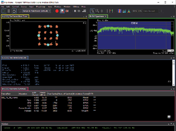
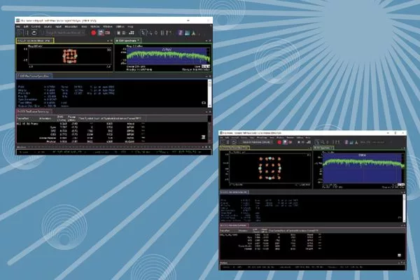
Figure 2 VSA Flex Frame demodulation results at 285 GHz for 30 GHz bandwidth signal.
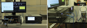
Figure 3 OTA quasioptic transmission at 285 GHz with 30 GHz bandwidth, transmit side.
Figure 2 shows the VSA Flex Frame demodulation results, using a 25 GHz IF with the VDI compact WR3.4 up-converter and down-converter with an LO multiplication factor of 12. An external IF amplifier used on the VDI down-converter output increases the IF signal level into the UXR.
The conducted demodulation results using VSA Flex Frame show the measured 16-QAM constellation in trace A and the measured spectrum at 285 GHz in trace B. The blue-shaded region of trace B in the spectrum measures the occupied bandwidth of 30.5 GHz. Trace C shows the residual composite EVM measurement of 5.89 percent. Trace D, at the bottom, shows the Flex Frame summary for the sync, SFD, CES, frame header and data payload frame allocations.
Gain Insight With OTA Measurements
The Keysight sub-THz test bed was used to investigate an OTA measurement at 285 GHz with 30 GHz bandwidth for a point-to-point transmission approaching 100 Gbps, transmitting over a distance of 26.5 ft. (8 m). High gain, high directivity antennas such as phased array antennas are necessary to overcome free space path loss. However, this was not possible because a 220 to 330 GHz phased array antenna was not available at the time of this experiment. Instead, quasioptic techniques were investigated using COTS lenses with performance specified to 220 GHz.
For this experiment, the test bed was split between a transmit section and a receive section. The transmit side of the test setup in Figure 3 consists of the M8199A AWG to generate the 25 GHz IF signal.
An E8267D PSG signal generator with option UNY provides a low phase noise LO at 21.666 GHz for the VDI up-converter. A VDI compact WR3.4 up-converter converts the 25 GHz IF from the M8199A AWG to 285 GHz using a multiplication factor of 12 (21.666 GHz × 12 = 260 GHz). The VDI WR3.4 270 GHz high-pass filter rejects the lower undesired image (260 GHz LO - 25 GHz IF = 235 GHz) while passing the desired image (25 GHz IF + 260 GHz LO = 285 GHz). The 285 GHz signal passes through a VDI WR3.4 amplifier and is then transmitted OTA with a VDI WR3.4 diagonal horn antenna.