
Ka-Band is susceptible to adverse weather conditions and therefore requires alternate/additional bands for seamless operation. It also has a greater number of orbital slots and capability for high capacity/density with smaller steerable beams. Ka-Band is resilient, using high data rates without degradation on smaller terminals and employs smaller antenna sizes than other bands (approximately ¼ size).
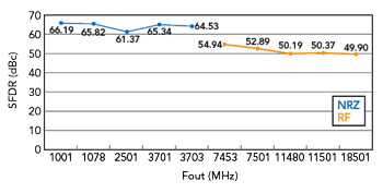
Figure 11 EV12DD700 SFDR vs. frequency.
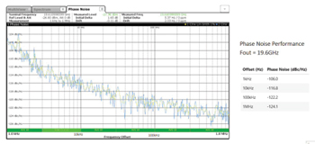
Figure 12 EV12DD700 phase noise.

Figure 13 EV10AS940 SFDR vs. frequency.
HPA
The HPA converts low-power RF signals (from the DAC) into high-power signals that drive the transmit antenna. Required specifications include gain, power output, output drive configuration (e.g., Class A, AB), bandwidth, efficiency, linearity (low signal compression at rated output), input/output impedance matching and heat dissipation. Each HPA component must be evaluated and understood from a multi-band simultaneous sampling performance perspective (as previously noted).
LNA
The LNA converts and amplifies very low-power RF signals from the antenna without significantly degrading signal to noise ratio and drives the receiver ADC. Required specifications include gain, noise figure, bandwidth, linearity, gain flatness, stability, input/output impedance matching and maximum RF input. An RF LNA must be low noise, high gain and have a sufficiently large intermodulation compression point (IP3 and P1db). An RF LNA must be protected by a power limiter to recover from large input signal transients that can occur during duplex switching (from Tx to Rx transitions).
Circulators/Switches (Duplexers)
RF duplexers enable bidirectional signal transmission through a single path (isolating the receiver from the transmitter and permitting them to share the same antenna). RF circulators enable full-duplex transceiver operations (transmitting and receiving at the same time with a single shared antenna over various frequencies). Ports are connected through waveguide transmission lines as well as microstrip line or coaxial cables. Specifications include frequency range, insertion loss, return loss, isolation, rotation and maximum power handling.
Waveguides/Filters
Waveguides are hollow metal pipes used as transmission lines connecting the transmitter and receiver to the antenna and the geometry of the waveguide structure can also serve as a filter to determine which frequencies are passed and which are rejected.
Clock Generator
The clock generator is an electronic oscillator that produces clock signals for use in synchronizing system-level operations. The clock generator must be programmable and provide enough drive for multiple copies to be distributed throughout the system. Specifications include frequency range, programmability, power drive, phase noise and jitter.
Optical Digital Harness
An optional optical digital harness may also be useful. It electrically isolates the system interconnections and enables further antenna digitization and weight reduction.
MEASURED PERFORMANCE
Figures 11 and 12 show SFDR and phase noise performance of the EV12DD700 DAC.
Figures 13 and 14 show SFDR and uncalibrated/calibrated performance of the EV10AS940 ADC.
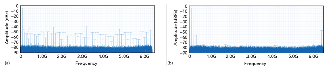
Figure 14 EV10AS940 frequency performance uncalibrated (a) vs. calibrated (b).
CONCLUSION
Microwave RF transceiver developers face design challenges for simultaneous sampling, multi-band and multi-service systems while adhering to SWaP-C constraints. In addition, the continuous release of next-generation ADCs, DACs and FPGAs impact hardware development plans driving frequent redesign.
Now, however, Tx and Rx data conversion components can achieve L- through Ka-Band capabilities and advanced SiP assembly technologies place the FPGA within the same package. These advances enable Teledyne e2v’s Tx/Rx MiXiP SiP design for microwave RF transceiver systems with software-defined flexibility and multi-band/multi-service capability. Teledyne e2v’s advanced MixSiP SiP design gives TAM designers the highest performance (up to Ka-Band) and value through a software-defined direct RF simultaneous sampling multi-band/multi-service transceiver.
References
- S. Lischi, R. Massini, R. Pilard, D. Stagliano and N. Chantier, “Feasibility Study of a Fully-Digital Multi-Band SAR System operating at L, C, X and Ku Bands,” 7th Workshop on RF and Microwave Systems, Instruments & Sub-systems + 5th Ka-band Workshop, May 2022.
- F. Deviere, N. Seller and J. Rohou, “Making History: Advanced System in a Package Technologies Enable Direct RF Conversion,” White Paper, Microwave Journal, Vol. 64, No. 1, January 2021.
- B. Dunbar and S. Caldwell, “9.0 Communications,” National Aeronautics and Space Administration, March 2022.
- R. Cohen-Hirsch, “Why Ka-Band Best Supports the Modern Miliary Mission,” MilsatMagazine, September 2015.
- T. O’Farrell, R. Singh, Q. Bai, K. L. Ford, R. Langley, M. Beach, E. Arabi, C. Gamlath and K. A. Morris, “Tunable, Concurrent Multi-band, Single Chain Radio Architecture for Low Energy 5G-Rans,” IEEE 85th Vehicular Technology Conference (VTC Spring), June 2017.
- S. Amin, P. Handel and D. Ronnow, “Characterization and Modeling of RF Amplifiers with Multiple Input Signals,” Conference: Swedish Microwave Days, March 2016.
- X. Yang, S. Li and F. Li, “Fourth-Order Nonlinear Distortion to the Power Spectrum of RF Amplifiers,” The Journal of Engineering: The Institute of Engineering and Technology, Vol. 2022, No. 1, January 2022, pp. 53–63.
- A. Patyuchenko, M. Younis, S. Huber, F. Bordoni and G. Krieger, “Design Aspects and Performance Estimation of the Reflector Based Digital Beam-Forming SAR System,” Conference: International Radar Symposium (IRS), April 2009.