

SDR systems use complex sampling, where an orthogonal, two-dimensional set of real and imaginary samples are accessible instead of a single real-valued set of signal samples. Complex sampling has several benefits over traditional sampling: Complex sampling enables unaliased signal processing up to the sampling rate, instead of the usual Nyquist limit of half the sampling rate. This minimizes ADC requirements and sampling rate limitations. Complex sampling performed by the SDR yields I/Q samples, which means the maximum instantaneous bandwidth equals the converter’s sampling rate. These devices can capture a signal band more efficiently, as it produces a spectrum representation without unnecessary symmetry and uses the ADC sampler more efficiently. Another benefit: with many M-ary digital communication modulations, the encoded signal has in-phase and quadrature components; by using a complex sampler, processing is simplified. Figure 2 illustrates complex sampling and how it differs from conventional sampling. When capturing spectral content, a complex sampling ADC halves the minimum sampling frequency rate compared to conventional sampling but doubles ADC operation and storage. Also, complex sampling does not exhibit conjugate symmetry, which must be considered when processing signals.
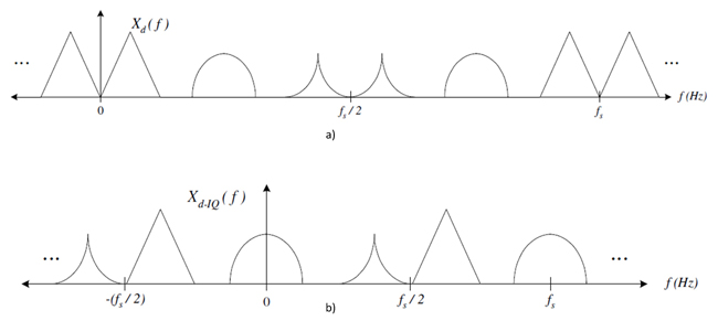
Figure 2 Discrete spectrum using conventional (a) and complex (b) sampling.
The VITA Radio Transport (VTR) standard defines the networking protocol for sending data packets from the SDR to other systems. The VRT standard, also known as VITA 49, enhances interoperability between RF systems and related equipment, defining a common format for sending and receiving digitized messages. Hierarchical, radio-description language VITA 49 is a novel radio architecture paradigm, using a packet-based protocol for transmitting digital data and metadata in high performance SDRs. This standard describes, stores and transports all spectrum information observed by a radio’s antenna. SDR devices encapsulate VITA 49 data in UDP, IP and Ethernet (Application > Transport > Internet > Link).
The VITA 49 standard is also important for time critical applications. For instance, GPS disciplined oscillators generate a pulse per second (PPS) signal to deliver precise timing, acting as a common clock for synchronizing multiple SDRs or other equipment. The PPS signal can be fed to a “REF IN” port on the SDR, which enables data samples to be tagged with specific sample clock counts in the VITA 49 header.
The network backhaul may limit the performance of an SDR. The network backhaul is how data from the SDR is sent to a host system or server and is important to ensure the functionality of high performance applications. An SDR’s data throughput stems from the network backhaul, i.e., how the Ethernet protocol is implemented and the number of physical transceiver connections. Typically, radio products are constrained by the maximum backhaul bandwidth, which is limited by the line rate of the bus linking the host machine and SDR. Figure 3 shows two examples of commercial SDRs with high data transfer capabilities, offering various ports for 10, 40 and 100 Gbps data transfer to external servers.
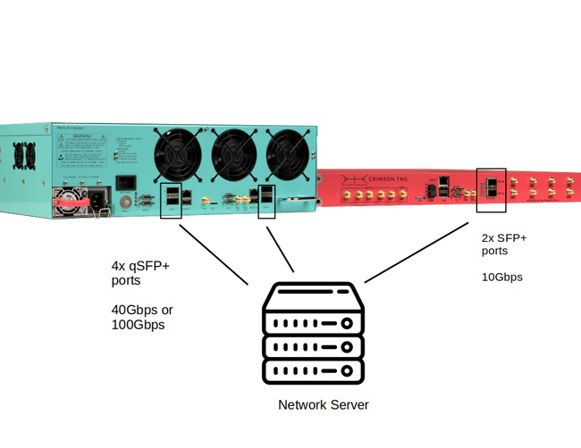
Figure 3 SDRs with high-level architecture are Per Vices Cyan (left) and Crimson TNG (right).
The dynamic range of the SDR is another important specification that is determined by several other performance metrics:
Noise floor — The noise figure is the ratio (in dB) of the receiver’s input noise power, which is present even when no signals are present. It is the sum of the thermal noise and the all the other noise sources and unwanted signals in an SDR system. The noise floor dominates receiver sensitivity.
Third-order intercept point (IP3) — Harmonics and intermodulation products caused by nonlinearity can cause problems. Spurious signals can disguise a weak, “interesting” signal by falling on the same frequency and masking the desired signal.
1 dB Compression — At some increasing signal level, RF amplifiers and mixers become nonlinear, as output stages cannot handle unlimited power levels. The 1 dB compression point is a good indication of the output signal becoming compressed and nonlinear.
Various measures are employed in SDRs and other receiver systems to improve dynamic range or sensitivity. One example is automatic gain control (AGC), which adjusts the receiver’s sensitivity for varying-amplitude signals using essentially a wideband DC amplifier (see Figure 4). AGC works by measuring the incoming signal level and supplying a proportional voltage to control the gain of the receiver’s amplifier stages so they won’t be overloaded. A well-designed AGC can prevent overload and creating spurious signals in the RF chain.
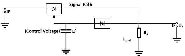
Figure 4 AGC circuit.
Another important capability of an SDR is MIMO. MIMO increases the capacity of a radio link by using multiple transmitting and receiving antennas to create spatial diversity. It can boost data transmission in spectrally constrained locations while reducing urban multipath effects and is used to avoid interference from microwave or RF systems in high bandwidth communications. MIMO uses multiple, separate Rx/Tx channels with coherent timing. The timing system in the SDR must ensure phase stability between channels, which is crucial for MIMO antenna arrays. SDRs with MIMO capability offer a cost-effective, multi-channel wireless infrastructure that supports contemporary waveforms and future MIMO processing.
SDRs FOR MILITARY APPLICATIONS
The radio spectrum is utilized for many military applications, from mobile phones, tactical radio, radar, satcom, EW, SIGINT and the related field of spectrum monitoring. Spectrum monitoring involves monitoring and analyzing RF data and consists of monitoring, recording and playback analysis. Spectrum monitoring is critical for spectrum management, safety and security, locating adversarial emitters and to ensure compliance. It also lends a hand to SIGINT, intelligence gained from an adversary’s electronic signals and systems, providing insight into foreign capabilities, activities and intentions.
Critical specifications for spectrum monitoring and SIGINT include instantaneous bandwidth (IBW), the frequency range that can be analyzed simultaneously. The IBW is determined by the filters in the instrument and the sample rate and bandwidth of the ADC. Traditional spectrum monitoring and recording equipment typically sweeps from low to high, with a low probability of intercept (POI) that renders them unsuitable for recording short-duration signals. Modern SDR equipment can capture a large bandwidth instantaneously and short-duration signals with high POI.
The RFE of an SDR must have the sensitivity to detect small signals and the dynamic range to avoid intermodulation products caused by high amplitude carriers within the same band. By implementing AGC, dynamic range and sensitivity can be improved. Data rate, storage space and data transmission efficiency are also important specifications for transferring and storing wide bandwidth data streams on a host system without dropped packets. Spectrum monitoring requires fast and efficient data flow, requiring data packetization into 100 Gbps Ethernet over QSFP+ transceivers, FPGA-accelerated NICs, high performance CPU/RAM and RAID-configured storage servers.
Signal spurs make it difficult to separate the signals of interest from noise and can compromise the data. SIGINT receivers must have exceptional dynamic range and spurious-free dynamic range (SFDR), which is the ratio of the fundamental signal to the strongest spurious signal in the output. SFDR represents the smallest signal that can be differentiated from a huge interfering signal, i.e., spurs resulting from IP3 and P1dB and non-ideal noise floor. MIMO is often used in direction finding applications for SIGINT and EW and requires multiple antennas pointed in different directions and many different frequency bands. SDRs with embedded algorithms on their FPGAs or in host systems are used for direction finding through angle of arrival, time-difference of arrival and phase difference of arrival. SDR enables geolocation of the adversary by MIMO antenna arrays and algorithms to locate RF emitters. The VITA 49 time stamps enable precise timing of received signals and UTC-synchronized data packets for precise measurements. Once the signals are digitized and stored on a host machine, various tools can be used for analysis, such as constellation diagrams, power meters, oscilloscopes and spectrum analyzers.
EW is an important capability that can aid and hinder efforts to achieve military, economic and diplomatic objectives. On the defensive side, military SDR must use low POI waveforms to evade detection and anti-jam designs to resist interference. On the offensive side, signal jamming is often used to send signals to intentionally interfere with a frequency used by the enemy. EW requires numerous radio capabilities, including fast sweeping and retuning time, the capacity to create and modulate signals with noise and wide or narrow band operation. Both noise and deception jamming can be accomplished with signal generation using the SDRs FPGA. Noise jamming includes transmitting a modified RF carrier at the target’s radar frequency to saturate the radar receiver and suppress its ability to determine range, azimuth and elevation data. Deception jamming processes and retransmits radar pulses using complex algorithms to spoof the radar’s ability to determine range, azimuth or velocity. High performance SDRs incorporate FPGAs that can digitally beamform RF radiation using MIMO antennas to jam a target.
Field-proven satcom technologies suit modern warfare needs, delivering secure and reliable connectivity on land, in the air or at sea, helping military personnel plan and cooperate in the multidomain field. Commercial and defense industries use satcom equipment for communication, including low Earth orbit satellites and constellations. Military satcom typically uses Ka-Band, which requires higher frequency tuning ranges. To ensure no data loss, the installed receivers must be sensitive enough to decode signals reduced by natural occurrences such atmospheric influences and fading. With scenarios like non-line-of-sight (NLOS), a sensitive receiving antenna may still lose the data. Here, MIMO technology offers a solution by providing redundancy without requiring additional resources, where SDR architecture can include MIMO with minimum per-unit cost. SDR technology can handle MIMO affordably, allowing a system to be deployed today with MIMO capabilities added later, making it attractive to use in satellite ground station phased-array radars.
SUMMARY
This article focused on the key specifications to ensure an SDR’s performance is matched with the intended military and aerospace applications. Key specifications include tuning range, IBW, protocol stack, backhaul bandwidth, dynamic range/sensitivity and MIMO functionality. Integrating an SDR adds versatility to communication systems through its reconfigurable hardware and high performance components, and it can provide optimal performance for spectrum monitoring, SIGINT, EW and satcom applications.