
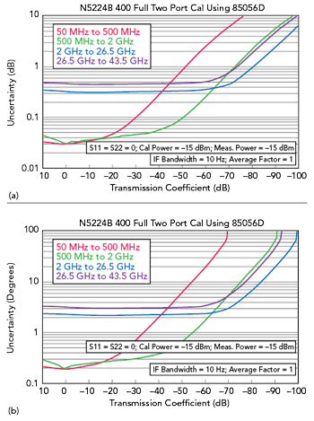
Figure 1 VNA transmission uncertainty: magnitude (a) and phase (b).1
A vector network analyzer (VNA) is as useful as the accuracy of the measurements it makes, and this requires the instrument to be calibrated. Very often those measurements need a test setup that includes not only the VNA and a calibration kit but also one or more measurement cables and adapters. The calibration process employs a technique called vector error correction, in which error terms are characterized using known standards so that errors can be removed from actual measurements. The process of removing these errors requires the errors and measured quantities to be measured vectorially (thus the need for a VNA). Directly after this calibration process, the best measurement accuracy can be expected. Changing anything may decrease measurement accuracy. Typically influences are temperature changes, bending/movement of the measurement cables, vibration and drift. This article concentrates on the measurement cables. It clarifies why and how cable bending and movement influence the accuracy and how measurement cables can be characterized to estimate their influence on the accuracy.
With vector error correction of the entire measurement setup, the transmission and reflection behavior of the measurement cables in magnitude and phase are mathematically removed. Subsequent movement of a measurement cable causes small internal dimensional changes, compression of dielectric materials, changing of contact resistances and shielding. All these effects may result in slight changes of the transmission and reflection behavior so that the vector error correction is no longer fully valid and measurement accuracy is decreased.
VNA MEASUREMENT UNCERTAINTY
For different branded microwave VNAs there are specifications for the “accuracy of measurements,” “typical accuracy” or “uncertainty” in tabular and/or graphical form. These values are valid for certain combinations of a VNA type and a calibration kit type and are limited to defined conditions such as source power level and temperature change. Measurement cables are typically not included.
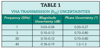
Values of “transmission uncertainty” for a higher end VNA in conjunction with a defined calibration kit are shown in Figure 1. Table 1 lists such uncertainties for an insertion loss range from 0 to 20 dB taken from Figure 1.
MEASUREMENT CABLE SPECIFICATIONS
Measurement cables specially designed for use with high-end VNAs are commonly called test port cables. They are intended for frequent use with movement and bending for adapting to specific test setups and are often armored to prevent damage from mechanical stress. Table 2 shows a selection of measurement cables that work up to 40 GHz. Besides hard specifications, (i.e. “maximum”), often “typical” values are mentioned, sometimes graded in the frequency range. Note that these specifications change with cable length and are valid for different bending conditions. Commonly used synonyms for “insertion loss stability” are “attenuation stability” and “amplitude stability.”
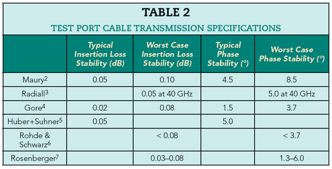
When comparing VNA transmission uncertainties in Table 1 with the measurement cable transmission specifications in Table 2, VNA S21 magnitude uncertainty corresponds to measurement cable insertion loss stability (typical or maximum), and VNA S21 phase uncertainty corresponds to measurement cable phase stability. If measurement cables are used on both VNA test ports, then cable specifications must be considered twice.
In this example, the measurement cable clearly dominates the phase influence at all frequencies and the magnitude at low frequencies. With two measurement cables, the magnitude at medium and higher frequencies is influenced similarly by the VNA and the measurement cables.
Reflection measurements are also influenced by measurement cables. Typically, the change in reflection magnitude is evaluated only and expressed as a return loss value. A detailed comparison between VNA uncertainties and measurement cable influence is not discussed here.
Depending on acceptable measurement uncertainties for a particular measurement task, it may be necessary to evaluate the influence of an individual measurement cable more specifically, for example in terms of frequency range and bending conditions, to reduce the total measurement uncertainty.
CABLE STABILITY MEASUREMENT DESCRIPTION
The most basic electrical properties of a measurement cable are insertion loss and return loss. Because the influence of cable stability is significant in VNA applications, the following describes how to characterize test port cable insertion loss, phase and return loss stability for VNA measurements.
Two Port Measurements
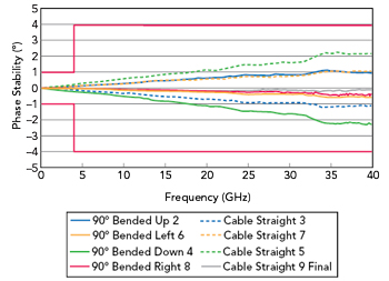
Figure 2 Phase stability vs. frequency.
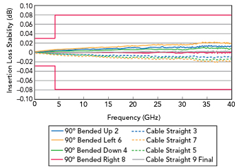
Figure 3 Insertion loss stability vs. frequency.
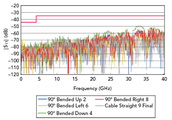
Figure 4 |S11| stability vs. frequency.
The most accurate way to do this is to use a two port VNA calibration with mechanically fixed test ports; however, this tolerates a very limited degree of freedom in bending and movement. This can be mitigated when the two test ports of the VNA are equipped with long, unfixed, measurement cables that are included in the VNA calibration. In this case, the measurement cables belonging to the VNA contribute their instability to the measurement.
One Port Measurements
One port measurements overcome these problems and provide freedom in bending and movement. Measurement cables belonging to the VNA are not necessary or can be fixed mechanically. Guideline VDI/VDE/DGQ/DKD 2622 Part 198 describes one port measurements with the measurement cable connected to a calibrated VNA test port.
Rosenberger uses a different method. The measurement cable is connected to the uncalibrated VNA test port and VNA calibration is performed at the free end. This setup is the same as for the intended use and provides some advantages in evaluating the results for transmission stability measurements, since the measurement uncertainty is significantly reduced. This is a benefit for longer cables and higher frequency bandwidths.
Transmission Stability
The basic setup terminates the free end of the measurement cable with a calibration standard short. This puts the measurement cable in the reference position and uses the VNA trace math to normalize the measured return loss and reflection phase on two different traces. The measurement cable is bent and moved to a different position as needed. The observed change in return loss and reflection phase must be divided by 2 to obtain insertion loss stability and phase stability. This is because the test signal emitted from the VNA travels through the measurement cable and is reflected back to the VNA by the calibration SHORT. It includes twice the cable transmission instabilities. The trace math function and all data processing can alternatively be done on an external PC.