
New Design
The team decided to redesign to reduce labor, complexity and cost. The antenna needed a symmetrical directional pattern to meet requirements. Based on our understanding of market direction, the team wanted to convert the design from a circular polarization to dual linear polarization, both horizontal and vertical. The gain of the first design fell short at 16 dBi, when 20 dBi gain was required.
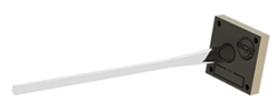
Figure 5 Dielectric rod antenna.
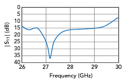
Figure 6 DWA return loss.
The new design was reconceptualized as a much smaller organic board (see Figure 4) that receives two orthogonal linearly polarized signals and converts to a dual polarized wave that is launched into a dielectric rod (see Figure 5). The return loss performance is shown in Figure 6. The results were:
• Low Cost - The team went to a multi-layered organic board and dielectric rod, which led to lower cost. The antennas were designed for low-cost connectors.
• Easier to Manufacture - The new design requires assembly of only three components and the team created a low-cost test procedure.
Optimized DWA
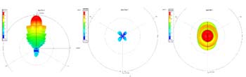
Figure 7 Original DWA: antenna pattern, xpol, end fire.
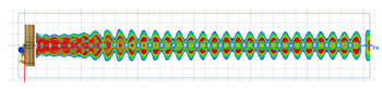
Figure 8 DWA radiation pattern.

Figure 9 Improved DWA patterns.
The lower taper angle, the lower base diameter and the upper rod diameter were all adjusted for optimum return loss, gain and minimum side lobes. The total rod length was adjusted for the necessary antenna beam width, 22.5 degrees for the FreeStar and optimized for maximum gain for the repeater (see Figure 8). A dielectric rod length of 5.6 in. achieved a gain of 19.5 dBi. Figure 9 shows the improvements in gain and reduction of the side lobes.
A Comparison: Beam Pointing and Phased Arrays
mmWave communications are limited by the high attenuation of the signal. Additionally, high frequency does not propagate well through materials, so the blockages and blind spots are numerous. The best results are achieved with line-of-sight between transmitter and UE. The effect of rain attenuation adds another dimension of complexity to network planning with mmWave. Finally, significant doppler shift appears at high UE speeds (coherence time ∝ λ2).
Despite the challenges, current and projected spectrum requirements make it difficult to visualize a future without mmWave; the amount of spectrum required to support projected wireless data consumption points to mmWave. A key element to making mmWave a success is the antenna. Unlike applications below 6 GHz, mmWave antennas must be integral to the electronics due to inherent cable losses that greatly degrade system performance so the type of antenna is key to a mmWave system.
There are key features that an ideal 5G mmWave antenna should have. First, the mmWave antenna should lead to a low cost, with minimal complexity and small form factor, especially for CPE devices. The mmWave antenna should be low power and dissipate as little heat as possible. The beam activation and switching should be in the hundreds of nanoseconds. The antenna should be dual polarized with a consistent beam gain and beam width, irrespective of UE location. The mmWave antenna should have an adaptive beam width depending on distance and user distribution. It should also support SU-MIMO and MU-MIMO operation. Lastly, the mmWave antenna should support multi-lobe beamforming to reduce impact of blockage.
Most designs for mmWave 5G rely on electronically steerable planar arrays. The planar array is composed of many antenna elements and each element requires phase shifters and power amplifiers (PAs) among other circuits. Telecom solutions typically require multiple panels, each partitioned into several subarrays.
Planar arrays have some drawbacks. First, planar arrays are made up of (up to) hundreds of antenna elements to produce narrow beams. Each panel requires tens to hundreds of antenna elements, phase shifters and PAs along with the electronics to power and control them. Panels are densely packed, making mechanical alignment, thermal management and control electronics a challenge to manage. That leads to high-power consumption and expense. Coverage can be inconsistent because beam widths and gain vary with the relative orientation of the UE to antenna. The antenna backlobe gain is almost as high as the main lobe gain, as shown in Figure 10. Phased arrays are complex with lots of circuit content needed per element, while the DWA requires a basic amp with the antenna.
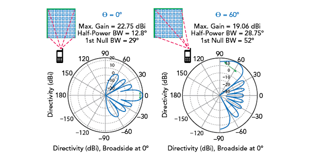
Figure 10 8 × 8 UPA with isotropic antennas, d = 0.5 λ, f = 28 GHz.
Finally, a planar phased array has limited support for single-user-MIMO and multi-user-MIMO functionality. To simplify design, each RF chain (MIMO stream) is typically connected to a specific subarray. This leads to limited flexibility in adapting MIMO streams based on spatial DOFs. The architecture leads to limited multi-lobe capability (one beam per RF chain). For MU-MIMO, more active UEs lead to a smaller subarray per UE and wider beam widths and lower antenna gain.
Empowering 5G Solutions Antennas
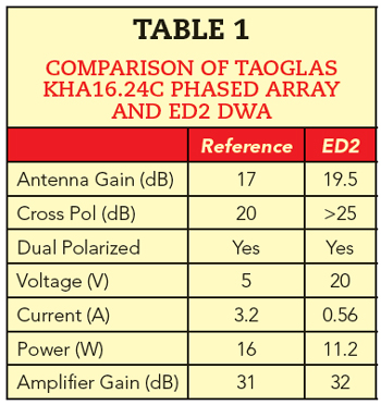
This DWA is a standalone, connectorized solution that can be used in any number of products. ED2 is partnering with world-class antenna manufacturers to guarantee performance and leverage cost efficiencies. Table 1 shows key performance parameters for DWA with a comparable mmWave phased array reference design offered by a leading antenna manufacturer.
Repeaters
In 2021, ED2 licensed its technology to Wilson Electronics with the intention of addressing the cellular repeater market. Together, the companies are producing a portfolio of repeater products that utilize ED2’s DWA technology in the FR2 space.
Advanced Antenna Systems (Freestar 5G)
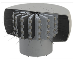
Figure 11 Fan-out base station concept with multiple polyrods (360 degrees azimuthal coverage, 60 degrees elevation coverage).
In 2020, ED2 designed and produced an Advanced Antenna System for Freefall 5G Inc., with the intent to address a variety of markets that take advantage of mmWave capability, like defense, radar, telecom and point-to-point or point-to-multi-point broadband.
The Freestar 5G antenna utilizes 16 individual cards, each with four DWAs, arranged circularly. The array is driven by a switch-matrix capable of connecting to four independent radio elements, any of which can be output to whatever desired antenna coverage patterns are needed for the application. Figure 11 shows a cutaway view of the Freestar 5G antenna.
The DWA offers significant advantages over state-of-the-art planar arrays. One DWA replaces a whole array/subarray, comprised of dozens of electronically steerable patch antennas, resulting in significant reductions in cost, power consumption (no phase shifters needed) and Si area. Furthermore, for use cases that involve servicing multiple users along different directions (e.g., street intersections), the incoming narrow-beam 5G signal from the gNB can be simultaneously fanned out by the repeater(s) through multiple DWAs. This switched-beam architecture, shown in Figure 3, does not require phase shifters. However, it requires a “switching matrix” that can turn on and off any subset of multiple beams at nanosecond speeds, and dynamically activate them in transmit or receive modes.
Field Measurements
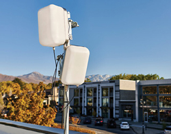
Figure 12 Wilson Electronics Network 257 mmW Repeater, using ED2 DWA technology.
The team has been testing with Wilson Electronics and Mobile Network Operators beginning in 2021, with extremely successful outcomes (see Figure 12). Most of the detailed results are confidential and cannot be shared publicly, but in field trials the repeater product has been proven to extend the range of a gNb and bend coverage into areas shadowed from RF signals.
A series of desert range tests were performed in Tucson, Ariz. A FreeStar stack module, which uses the DWA elements, was used as the transmitting device. A low QAM OFDM signal was transmitted at the start point and an ED2 repeater device was used as the receiver. Several way points were taken along the path to verify signal integrity. A range of 2.91 miles (4.68 km) was achieved before the team reached the limits of the testing ground. The test team verified that no multipath issues were present on the nearly 3-mile stretch of desert dirt road while maintaining a 15 to 20 dB SNR with a QPSK signal.
Beyond 5G
The DWA antenna approach can work across the entire mmWave spectrum. As of this writing, the 60 GHz spectrum is receiving a lot of attention, in part because of Meta. The DWA is a good solution for 60 GHz band as the interface would be a direct waveguide to a much smaller rod. Another potential application is the use of multi-frequency band DWA’s pointing at a particular fixed point. These and other ideas are part of the company’s research and development efforts.
Conclusion
Electronically steerable antenna arrays have been a popular choice for analog beamforming in 5G systems, due to the ease of integrating them with RFICs, the market advantages to Si providers who support the architecture and earlier deployments of phased arrays at lower frequencies. They are particularly suited for very narrow beamwidth applications under high mobility. DWA technology presents an alternative approach to phased arrays for use cases involving moderately narrow beamwidths (e.g., 20-degree nominal HPBW) and pedestrian speeds or fixed wireless applications. For these types of cases, phased arrays’ flexibility in beam steering becomes overkill, especially when considering the associated cost, complexity (tens to hundreds of antennas and phase shifters), high-power consumption, antenna pattern/gain inconsistency. The cost, performance and complexity advantages of DWA will enable them to play a role in delivering on the promises of 5G.
References
- G. Mueller and W. Tyrrell, “Polyrod Antennas,” Bell Labs, October 1947, Web: www.bell-labs.com/institute/publications/bstj26-4-837/#gref.
- “Samsung Announces 5G Data Breakthrough,” May 2013, Web: https://phys.org/news/2013-05-samsung-5g-breakthrough.html.