

UWB RECONFIGURABLE DRA
Abioghli et al.71 developed a reconfigurable DRA antenna, with dimensions 40 × 40 × 7.3 mm3. The ground plane was constructed by connecting an L-shaped stub and cutting two slots. It used a T-shaped DR of Rogers RT6010 with relative permittivity εr= 10.2 placed on a 1.6 mm thick FR4 substrate (see Figure 8). Reconfigurability was achieved with a PIN diode that modified the current distribution path in the ground. The diodes were biased at 0.7 V and a suitable impedance match was provided for the 17 mm ground length. Further work by Abioghli et al.72 on narrow band reconfigurable DRAs for cognitive radio application has been reported.
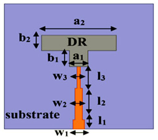
Figure 8 T-shaped reconfigurable DRA.71
OTHER UWB DR SHAPES
Sankaranarayanan et al.73 proposed a unique and compact modified Koch snowflake DRA geometry for broadband use. The radius and height of the cylindrically shaped DRA (CDRA) were 2.68 and 1.5 cm, respectively. An FR4 substrate was used with a ground plane of 10 × 10 cm2. Initially, a Koch snowflake design was developed on a basic CDRA (see Figure 9); however, a fractal ring structure was used to increase the overall impedance bandwidth and gain. The DRA covered the microwave frequency band from 4.7 to 12.4 GHz for a 90 percent bandwidth. Furthermore, the final geometry yielded a 76.6 percent reduction in DRA size. It had a 78 percent radiation efficiency across the entire impedance bandwidth with a maximum gain of 8.76 dBi. Other DRA shapes, such as bi-cone shaped, laterally fixed cylindrical, Turtle-shaped, T-shaped and E-shaped have also been investigated.74-80
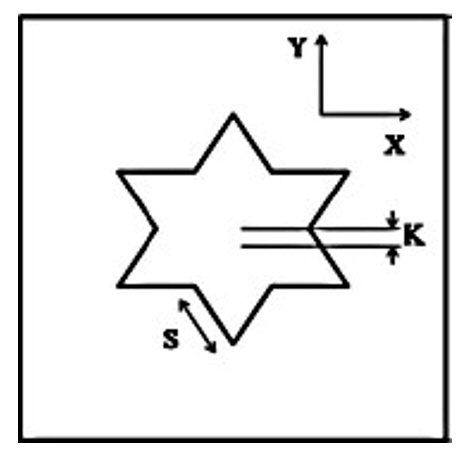
Figure 9 Modified Koch snowflake DRA.73
A proposed rectangular DRA designed for UWB applications is shown in Figure 10.80 It comprised a cylindrical air gap based RDRA, modified ground plane and metallic strips on a Rogers 5880 substrate. A cylindrical DR (CDR) with a diameter of 2xD1 enhanced its gain and bandwidth, and metallic strips improve its impedance characteristics. The antenna's near field supported dominant, second and third-order TE modes for a wide 103.9 percent impedance bandwidth covering the frequency range from 3.28 to 10.4 GHz.
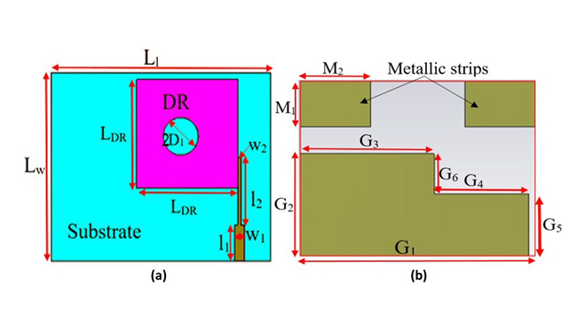
Figure 10 Air-spaced RDRA (a) with modified ground (b).80
ELLIPTICALLY OR CIRCULARLY POLARIZED UWB DRA
Haraz et al.81 described a half-cylindrical DRA (HCDRA) with CP characteristics for UWB applications. The HCDR was mounted on a finite ground plane on the bottom side of the substrate (see Figure 11a). The impedance bandwidth of the antenna was 90 percent covering the frequency range from 4 to 10.5 GHz. It exhibited an axial ratio bandwidth of 27 percent from 5.3 to 7 GHz.
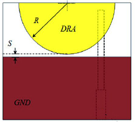
Figure 11a Half-cylindrical CP DRA81
Chakraborty et al.82 described a dual-band antenna covering 3.7 to 4.4 GHz (17.28 percent bandwidth) and 5.8 to 6.2 GHz (11.56 percent bandwidth). It consisted of a pair of symmetrically positioned DRs on a flat I-shaped monopole. The fundamental modes were excited at 3.8 and 6 GHz to generate CP with the DRs placed orthogonally on the substrate (see Figure 11b).
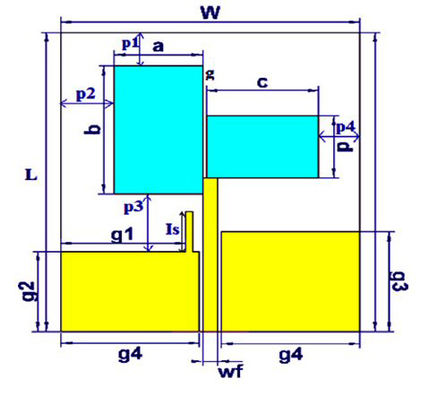
Figure 11b DRA with symmetrically positioned DRs82
Yadav et al.83 achieved UWB performance with an OM-shaped DRA and DGS (see Figure 11c).83 It covered a frequency range from 3.1 to 11.1 GHz with a peak gain of 7.68 dB and reported a band from 6 to 11.1 GHz with elliptical polarization characteristics.
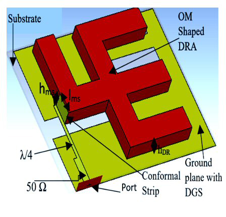
Figure 11c OM-shaped DRA with DGS83
UWB MIMO DRA
Abedian et al.84 designed a WLAN band rejection MIMO DRA. It was compact with dimensions of 29 × 29 × 5 mm3 and utilized a Taconic-35 substrate (see Figure 12a). A ground stub was used to improve isolation as well as impedance matching, and two L-shaped parasitic strips created a notch in the WLAN band from 5.15 to 5.85 GHz. The length and width of the strips could be adjusted to create a notch from 4.98 to 6.08 GHz. The compact DRA provided a broadside radiation and an impedance bandwidth of 106 percent (3.29 to 10.74 GHz), high radiation efficiency, and an ECC < 0.16.
Yadav et al.85 proposed a rack-shaped DRA with an inverted T-shaped parasitic strip designed for UWB applications. This MIMO antenna consisted of two radiators, a partial ground, stub and parasitic strip (see Figure 12b). Two DRA designs (one with and one without a parasitic strip) demonstrated impedance bandwidths of 72.67 percent (4.8 to 10.28 GHz) and 101.87 percent (3.54 to 10.89 GHz) with isolations greater than 21 and 15.6 dB, respectively. Reported diversity parameters were: directive gain (DG) ≥ 9.93 dB, TARC, group delay, ECC ≤ 0.0059 and channel capacity loss within the limits.
Sani et al.86 presented a stair-shaped rectangular DRA for UWB applications. The measured input impedance bandwidth of the antenna was 153.6 percent (1.6 to 12.2 GHz) with a minimum of 25 dB isolation between the radiators in the operating band. It demonstrated a low ECC and low mutual coupling throughout the desired frequency range.
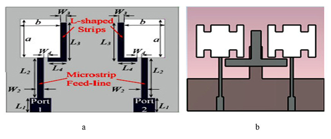
Figure 12 (a) Two-port MIMO DRA loaded with L-shaped strip84 (b) rack-shaped MIMO DRA with inverted T-shaped strip85
A two-radiator, element-based, MIMO with cross-shaped metallic parasitic strips (MPS) and an inverted T-shaped parasitic strip were designed for improved isolation as well as impedance bandwidth for UWB.87 The antenna consisted of two DRs, a partial ground with a scissor-shaped DGS, stub and parasitic strip (see Figure 13). Its impedance bandwidth of 104.6 percent covered the frequency band from 3.3 to 10.8 GHz. A cross-shaped metallic strip placed on the RDRA improved isolation, which was greater than 20 dB within the band. Its reported DG was 9.98 dB and ECC was 0.0059.
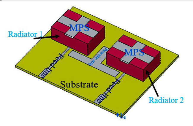
Figure 13 RDRA loaded with cross-shaped MPS.87
CONCLUSION
The basic geometries of DRAs are rectangular, cylindrical and hemispherical. Various shapes of DRs, DGS, modified grounds, parasitic elements, stubs, arrays and other techniques are used in the examples discussed to achieve UWB performance.
References
1. Revision of Part 15 of the Commission's Rules Regarding Ultra-Wideband Transmission Systems, FCC 02-48, Federal Communications Commission, 2002.
2. R. S. Kshetrimayum, “An Introduction to UWB Communication Systems," IEEE Potentials, Vol. 28, No. 2, March-April 2009, pp. 9-13.
3. Z. Guo, H. Tian, X. Wang, Q. Luo and Y. Ji, “Bandwidth Enhancement of Monopole UWB Antenna with New Slots and EBG Structures,” IEEE Antennas and Wireless Propagation Letters, Vol. 12, November 2013, pp.1550-1553.
4. M. K. Shrivastava, A. K. Gautam and B. K. Kanaujia, “An M‐Shaped Monopole‐Like Slot UWB Antenna,” Microwave and Optical Technology Letters, Vol. 56, No. 1, November 2013, pp. 127-131.
5. J. K. Plourde and C. -L. Ren, “Application of Dielectric Resonators in Microwave Components,” IEEE Transactions on Microwave Theory and Techniques, Vol. 29, No. 8, August 1981, pp. 754-770.
6. S. J. Fiedziuszko and S. Holmes, “Dielectric Resonators Raise your High-Q,” IEEE Microwave Magazine, Vol. 2, No. 3, September 2001, pp. 50-60.
7. C. Wang and K. A. Zaki, “Dielectric Resonators and Filters,” IEEE Microwave Magazine, Vol. 8, No. 5, October 2007, pp. 115-127.
8. K.M. Luk and K.W. Leung, Dielectric Resonator Antennas Handbook, Hertfordshire: Baldock, 2003.
9. A. Petosa, Dielectric Resonator Antenna Handbook, Artech House, 2007.
10. R.S. Yaduvanshi and H. Parthasarathy, Rectangular Dielectric Resonator Antennas, Springer, 2016.
11. M. W. McAllister, S. A. Long and G. L. Conway, “Rectangular Dielectric Resonator Antenna,” Electronics Letters, Vol. 19, No. 6, March 1983, pp. 218-219.
12. R. K. Mongia and A. Ittipiboon, “Theoretical and Experimental Investigations on Rectangular Dielectric Resonator Antennas,” IEEE Transactions on Antennas and Propagation, Vol. 45, No. 9, September 1997, pp. 1348-1356.
13. G. P. Junker, A. A. Kishk, A. W. Glisson and D. Kajfez, “Effect of Air Gap on Cylindrical Dielectric Resonator Antenna Operating in TM/Sub 01/Mode,” Electronics Letters, Vol. 30, No. 2, January 1994, pp. 97-98.