

Techniques, geometries, fabrication technologies and materials with ultra-wideband (UWB) characteristics for dielectric resonator antennas (DRA) are discussed. DRAs are placed on ground planes or dielectric substrates (rigid or flexible) and excited by different feed mechanisms. With the development of rectangular, cylindrical and other geometries, the fundamental goals are electrical size miniaturization, greater bandwidth to meet commercial requirements and radiation pattern stability. The focus is on applications related to portable devices, handheld devices, radio base stations, radar and satellite communication. The novel 'OM'-shaped air-spaced DRA, cross-shaped parasitic strip-based MIMO rectangular DRA and rack-shaped MIMO DRA for UWB applications are also addressed.
Compact UWB antennas have recently been investigated for wireless communication systems. In 2002, the Federal Communications Commission (FCC) allowed a UWB range of unlicensed bands from 3.1 to 10.6 GHz.1 For a UWB system, a broadband antenna is required. The challenges of UWB antenna design include impedance matching, compactness (size), radiation stability and low cost. Several types of UWB antennas were proposed.2,3
Since the development of low-loss ceramics in the 1960s, dielectric resonators (DRs) have been used in microwave circuit applications.4-6 Early research to determine the resonant frequencies of DRs resulted in advances in the design of antennas utilizing such resonators as antennas. The DRA has attracted much attention over the last two decades because of its many attractive features such as low profile, high radiation efficiency, low conductor loss, light weight, ease of fabrication and low cost.7-10
DRAs are available in various forms, such as: rectangular, cylindrical, triangular, L-shaped, conical, T-shaped, trapezoidal, A-shaped, E-shaped, P-shaped, C-shaped, F-shaped, H-shaped U-shaped, V-shaped, Z-shaped and super-shaped.11-25 Size and bandwidth are controlled by changing the material permeability (εDR). Being a 3D radiating structure, it enjoys greater design flexibility and adaptability than conventional antennas.
Short-range communication operates in a rich scattering environment, which can cause fading due to multipath, power loss due to disintegrating conditions or mismatches due to transmitter-receiver antenna orientation.26 A DRA can easily produce circular polarization characteristics through various techniques such as: shape modification, metallic strips, cross-slot-coupling and single/dual feeding structures.27-30
In recent years, there has been an increasing demand for MIMO antennas with high data rates, high reliability, high channel capacity, low channel interference and low envelope correlation coefficient (ECC).31-34 MIMO DRAs can be categorized by single or multiple radiator elements. A two DR radiator element was chosen in the MIMO system described by Das et al.35 MIMO diversity parameters such as ECC, mean effective gain and total active reflection coefficient were calculated.35
DRAs are used in various configurations to provide significant improvements in bandwidth, radiation efficiency and gain as well as reduced antenna size. The number of papers related to UWB DRAs published between 2005 to 2021 (see Figure 1) shows an increasing interest in this area.
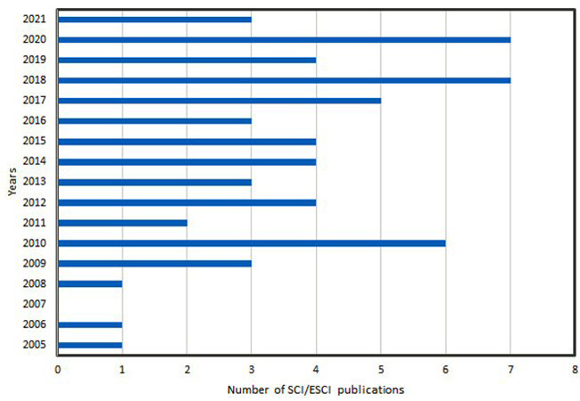
Figure 1 UWB DRA papers published per year.
The most common DRA shapes are cylindrical, rectangular and hemispherical. DRA resonant mode excitation depends upon input excitation, cavity volume and boundary conditions. Standing waves are generated based on these parameters at resonance. The standing waves are converted into traveling waves due to transparent walls (boundary conditions). Resonant modes such as TE, TM, TEM, HE and HEM can be excited. These are also known as transverse electric, transverse magnetic and hybrid modes. Fundamental or higher order modes can be excited, such as (TE111–TElmn) and (TM111–TMlmn).10 UWB performance can be achieved through mode merging. Modified shapes and the use of defective ground structures (DGS), stubs and other techniques are also used to enhance antenna performance.
The following sections describe some of the techniques used to design UWB DRAs. Examples are also presented, addressing their advantages and disadvantages.
UWB DRA BASED ON A THIN MONOPOLE
A monopole-loaded single annular ring DRA with the same axial reference was designed for UWB applications by Lapierre et al.36 The cylindrical DR was set on a finite ground plane and excited by a probe fed with a quarter-wave monopole (see Figure 2). Prototype Antenna #1 covered a frequency range between 6.3 and 16.2 GHz with Εr1 = 10 and L = 10 mm. Prototype Antenna #2 covered a frequency range between 4.2 and 10.1 GHz with Εr2 = 20 and L = 15 mm. Results for several other monopole DRAs have also been reported.37-48
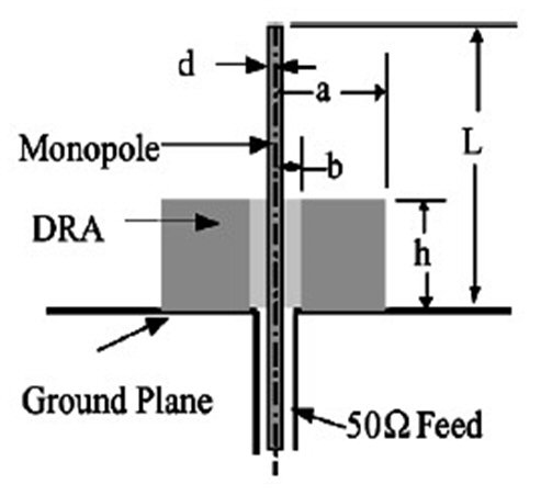
Figure 2 Single annular ring DRA.36
UWB ELECTROMAGNETICALLY COUPLED DRA
Denidni and Weng49 introduced a new rectangular-shaped DRA (RDRA) for UWB applications. The RDRA comprised a DR excited by a bevel-shaped patch coaxial feed, providing an air gap between the DR and the infinite ground plane (see Figure 3). The 27.2 × 12.6 × 19.1 mm3 RDR made of Rogers TMM 10i was mounted on a 75 × 90 mm2 ground plane. The Q-factor and effective permittivity were reduced by the air gap and bevel-shaped feed, providing mode transition and the widening bandwidth. Radiation efficiency of the antenna in the operating band was greater than 90 percent. Its reported impedance bandwidth was 120 percent (2.6 to 11 GHz). Many other authors have also published electromagnetically coupled DRAs for UWB operation.50-52
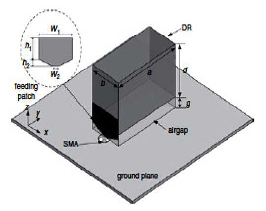
Figure 3 Rectangular DRA with the air gap.49
UWB PATCH-BASED DRA
Aoutoul et al.53 investigated a compact RDRA with permittivity εr= 10.2 with a low profile substrate of permittivity εr=3 and modified ground. The 10 × 10 × 2.5 mm3 RDR sat on a 30 × 45 ×1.27 mm3 substrate. The dimensions of the truncated ground plane were 30 × 25 mm2 (see Figure 4). A 3.94 × 3.94 × 1.2 mm3 metallic layer was placed beneath the DRA to improve its bandwidth (31 percent, 6.86 to 9.41 GHz) and impedance matching. An impedance bandwidth of 46 percent (6.9 to 11 GHz) was achieved using a stepped slot in the ground plane. Other patch-based DRA designs developed for UWB applications have been reported.54-57
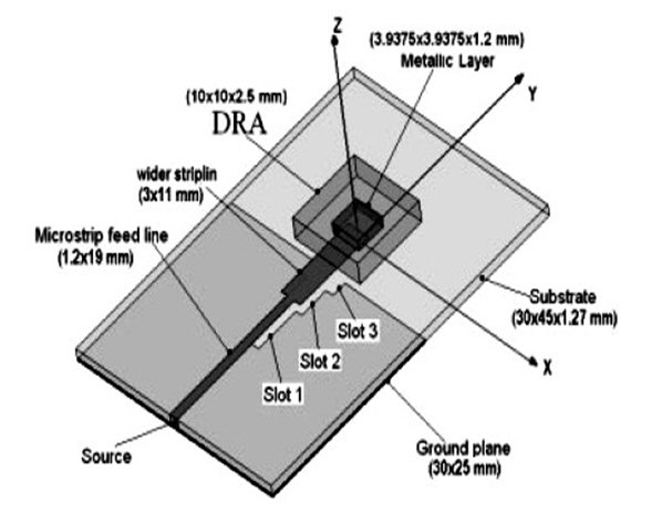
Figure 4 Compact RDRA.53
UWB INSERTED DRA
Ryu and Kishk58 described a novel portable DRA for UWB wireless applications. The antenna provided a broadside radiation pattern using a solid RDR mounted on the edge of a vertical ground plane. The total size of the DRA was 18.3 × 14 × 5.08 mm3. It had a 10.2 permittivity and was bonded to an RT6002 substrate. Its impedance bandwidth was 84 percent. A wide impedance bandwidth (93 percent from 3.5 to 9.6 GHz) was obtained with a modified version of the RDR, which consisted of two dielectric fragments configured into an A-shape (see Figure 5). Similar structures have been reported by other researchers.59
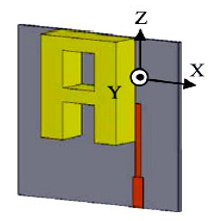
Figure 5 A-Shaped DRA with modified ground.58
UWB DRA WITH BAND REJECTION CHARACTERISTICS
Sabouni et al.60 proposed an A-shaped DRA for UWB applications. The radiating element was excited by a transformer type of microstrip feed printed on the substrate. It covered 3.5 to 10.5 GHz, which supports the UWB range. Shorted stubs produced the notch features of the antenna. These elements were parasitically coupled to the feedline (see Figure 6). Two notches were created in the UWB when two U-shaped parasitic elements were used with lengths of 8.96 and 10.65 mm, and a width of 1 mm. The peak gain of the antenna was 5.46 dB without a notch. UWB DRAs with band notch characteristics have been investigated by several researchers.61-63
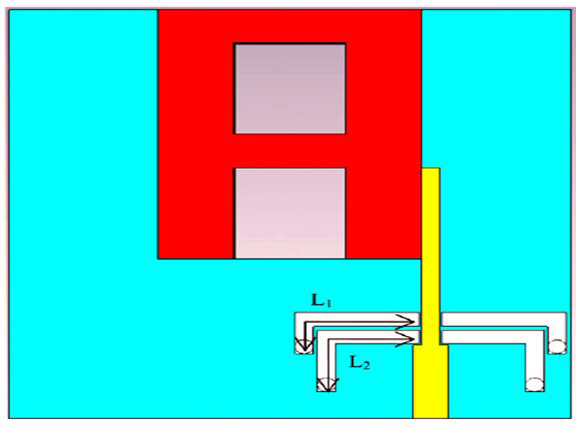
Figure 6 A-shaped DRA with U-shaped parasitic elements.60
UWB STACKED OR SEGMENTED OR COMPOSITE DRA
Ge et al.64 designed a rectangular DRA for UWB operation. The RDRA exploited multiple low-Q modes with overlapping bandwidths to achieve a wide contiguous bandwidth. This was achieved using a full-length, low permittivity, insert between a higher permittivity dielectric volume and a ground plane (see Figure 7a). The volume of the DR was reduced with a finite conducting wall fixed on the side of the DR layer. The impedance bandwidth of the DRA was 110 percent from 3.1 to 10.7 GHz.
Kshirsagar et al.65 proposed a two-segment RDRA combination of half-size RDRAs made up of materials placed side-by-side with εr= 4.3 and εr= 9.2 and excited by a common microstrip feed (see Figure 7b). The effect of a defected ground was also investigated. A parametric study of the DGS angle was conducted at 0, 30 and 45 degrees. The antenna covered the UWB at an angle of 45 degrees from 2.9 to 11.6 GHz (120 percent bandwidth). The antenna exhibited a peak gain of 7.2 dBi. Many authors have used this same concept for enhancing the antenna characteristics.66–70

Figure 7 Stacked DRA with LPI64 (a) and RDRA based on a patch or conformal strip65 (b).