
2/3 Divider Cell with MS-DFF and XOR Gate (MMPFD-2)
To further decrease power consumption and die size, a 2/3 divider cell comprising two MS flip-flops and an XOR gate are used (see Figure 5a). Compared to MMPFD-1, fewer D flip-flops result in less time delay, lower power consumption and higher operating frequency. When PB = 0 and Modin = 0, the 2/3 divider cell works as a divide by 3 cell (see Figure 5b). When PB =1 and Modin = 1 or PB = 0 and Modin = 1 or PB = 1 and Modin = 0, the 2/3 divider cell works as a divide by 2 cell (see Figure 5c).
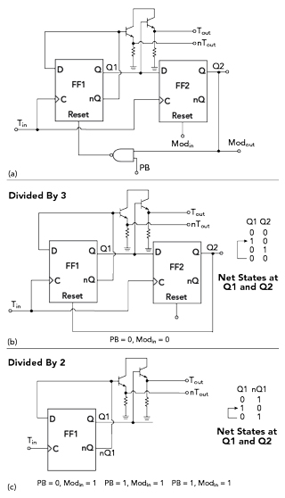
Figure 5 MMPFD-2 2/3 divider cell (a) and simplified configuration and state diagram when set to divide by 3 (b) or divide by 2 (c).
Figure 6 Fabricated dividers.
EXPERIMENTAL RESULTS
The frequency dividers were implemented in a 2 μm GaAs HBT process (see Figure 6) and measured with an oscilloscope for verification (see Figure 7). Without bonding pads, the core areas of MMPFD-1 and MMPFD-2 are 0.56 × 4.4 mm and 0.52 × 2.91 mm, respectively. MMPFD-1 draws 175 mA current with a 5 V supply, while MMPFD-2 only draws 112 mA. Figure 7a shows representative output waveforms from each divider. As shown in Figure 8, compared with the traditional prescaler and operating at the same frequencies, the power dissipation of MMPFD-1 is reduced by up to 180 percent while the power dissipation of MMPFD-2 is reduced by 240 percent, and a more compact die is possible.
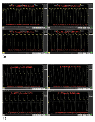
Figure 7 Representative output waveforms from the MMPFD-1 (a) and MMPFD-2 (b).
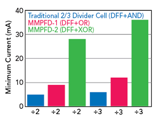
Figure 8 Comparing minimum current with 3 GHz input.
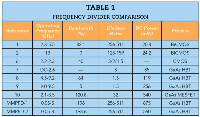
Table 1 compares this work with other published work when this article was written. In general, frequency dividers designed in Si bulk technologies (i.e., CMOS and BiCMOS)1,2,6 have lower DC power dissipation, but technology shortcomings may eliminate them from use in applications needing very low phase noise and radiation resistance. Compared to some reported frequency dividers using compound semiconductor processes,7-10 these MMPFDs achieve the widest division ratios and they have the largest bandwidths compared with other reported dividers.
CONCLUSION
Two MMPFDs based on 2 μm GaAs HBT technology demonstrated a wide division range with the divide ratio varying continuously from 256 to 511. The MS flip-flop used to construct the 2/3 divider cell was modified so that it is supplied by a single tail current source. As a result, the GaAs HBT structure consumes less power and is more compact. It may be employed in fully integrated PLL applications such as fractional-N frequency synthesizers and agile frequency synthesized sources.
References
- W. Li, H. Chen and R. Yao, “ A 5.5-GHz Multi-Modulus Frequency Divider in 0.35 μm SiGe BiCMOS Technology for Delta-Sigma Fractional-N Frequency Synthesizers,” IEEE International Conference on Microwave & Millimeter Wave Technology, May 2010.
- M. Ray, W. Souder, M. Ratcliff, F. Dai and J. D. Irwin, “A 13 GHz Low Power Multi-Modulus Divider Implemented in 0.13 μm SiGe Technology,” IEEE Topical Meeting on Silicon Monolithic Integrated Circuits in RF Systems, January 2009.
- C. S. Vaucher, I. Ferencic, M. Locher, S. Sedvallson, U. Voegeli and Z. Wang, “A Family of Low-Power Truly Modular Programmable Dividers in Standard 0.35-um CMOS Technology,” IEEE Journal of Solid-State Circuits, Vol. 35, No. 7, August 2000, pp. 1039–1045.
- S. Y. Wang, X. L. Wu, J. H. Wu and M. Zhang, “Low Power Design of Multi-Modulus Programmable Frequency Divider,” Electronics Letters, Vol. 45, No. 20, September 2009, pp. 1017–1019.
- H. Wang, P. Brennan and D. Jiang, “A Generic Multi-Modulus Divider Architecture for Fractional-N Frequency Synthesizers,” IEEE International Frequency Control Symposium Joint with the 21st European Frequency and Time Forum, May-June 2007.
- D. Guermandi, P. Totori, E. Franchi and A. Gnudi, “A 0.75 to 2.2 GHz Continuously-Tunable Quadrature VCO,” Proceedings of the IEEE International Solid-State Circuits Conference, February 2005, pp. 536–537.
- S. C. Tseng, C. C. Meng and W. Y. Chen, “SSH and SHH GaInP/GaAs HBT Divide-by-3 Prescalers with True 50% Duty Cycle,” Electronics Letters, Vol. 42, No. 14, July 2006, pp. 796–797.
- H. Shin and B. Won, “A 4.5 to 9.2 GHz Wideband Semidynamic Frequency Divide-by-1.5 in GaInP/GaAs HBT,” IEEE Microwave and Wireless Components Letters, Vol. 17, No. 1, January 2007, pp. 73–75.
- B. Won, J. Shin, S. Jeon and H. Shin, “A 9 GHz Semidynamic Frequency Divide-by-2/3 in GaInP/GaAs HBT,” Asia-Pacific Microwave Conference Technical Digest, December 2005, pp. 1612–1615.
- K. Osafune and K. Ohwada, “An Ultra-High-Speed GaAs Prescaler Using a Dynamic Frequency Divider,” IEEE Transactions on Microwave Theory and Techniques, Vol. 35, No. 1, January 1987, pp. 9–13.