
The current capabilities of the RF Systems Test Facility at MIT Lincoln Laboratory for rapid prototyping and measurements of antennas, radar targets and electromagnetic systems are described. The facility has six shielded anechoic chambers consisting of a low frequency tapered chamber, mmwave chamber, small near-field scanner, system test chamber, compact range and large near-field scanner. An on-site machine shop, RF laboratory and system integration laboratory have significant roles in the rapid prototyping process at the RFSTF. RF measurements of phased arrays and other types of RF measurements are described.
I. INTRODUCTION
The MIT Lincoln Laboratory RF Systems Test Facility (RFSTF) depicted in Figure 1 is a research and development rapid prototyping facility with resources to design, fabricate and measure antennas, radar targets and electromagnetic systems for surface, airborne and space applications. The initial operating capability of the RFSTF was established in 2004 with four anechoic chambers as previously described.1-3 Since then, two planar near-field scanning anechoic chambers and spherical near-field scanning capability have been added to the facility. The RFSTF currently comprises six anechoic chambers, a system integration laboratory (SIL), high-bay staging area/rapid prototype shop, and the RF Laboratory. The RFSTF is co-located with the MIT Lincoln Laboratory Flight Test Facility, which allows rapid integration of RF sensors with airborne platforms.
The six shielded anechoic chambers (tapered, mmwave, small near-field scanner, system test, compact range and large near-field scanner) enable antenna, radar cross section (RCS), and electromagnetic systems measurements over a wide frequency range. The three large system test, compact range and large planar near-field chambers can accommodate large, heavy, test articles, making use of an overhead crane (system test chamber), rolling gantry with crane (compact range chamber), and reconfigurable rolling cart (large near-field chamber). The system test rectangular chamber provides far-field and spherical near-field scanning capabilities up to 20 GHz. Antenna and RCS measurements are performed in the compact range from UHF up to 100 GHz with a blended rolled-edge reflector and multiple feed horns. The large near-field scanner chamber is configured to calibrate and measure gain radiation patterns of large phased array antenna apertures up to 50 GHz. In the tapered chamber, a dual-polarized ultrawideband feed allows measurements from 250 MHz up to 3 GHz, and higher frequencies. The rectangular mmwave chamber operates up to 100 GHz. The small near-field scanner chamber is used primarily for calibrating and testing small phased array antenna panels or reflector antennas up to 26 GHz. Rapid prototyping of antennas, radar targets and electromagnetic systems is facilitated with electromagnetic simulation software.
This article is organized as follows. Sections II to VII describe each of the RFSTF chambers. Example RFSTF measurements of phased arrays and other antennas are described. Section VIII describes the rapid prototyping shop, RF lab and system integration lab. Section IX is a summary.
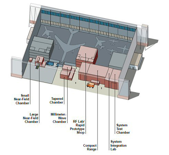
Figure 1 RF Systems Test Facility at MIT Lincoln laboratory.3
II. LOW FREQUENCY TAPERED CHAMBER
The RFSTF low frequency tapered chamber (see Figure 2) is EMI shielded and has a range length of R = 8.5 m to the center of the test zone, with a rectangular section 4.3 by 4.3 m in cross section by 5.1 m in length. The tapered chamber uses an ultrawideband dual-polarized conical tip feed4 developed by the Ohio State University that is designed to cover the 250 MHz to 3 GHz band and higher frequencies. The walls of the tapered chamber are covered with wedge absorber varying in height of 20 cm near the conical tip to 46 cm approaching the test zone. The test zone region uses 0.6 m pyramidal absorber. The back wall is covered with 1.8 m pyramidal absorber. The shielded conical tip region is 1.8 m in length with a 30 degree full cone angle. The conical tip houses two wideband 180 degree hybrids that provide a balanced feed to an orthogonal pair of ultrawideband flared launchers. Wedge absorbers provide a smooth transition toward the dual-polarization feed region. A custom RF switch box is used to manually control the feed excitation for vertical or horizontal polarization.
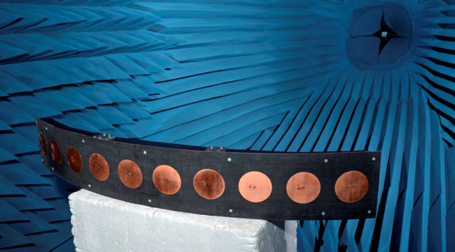
Figure 2 RFSTF tapered chamber with L-band 3D printed and copper plated conformal array antenna under test.5 The wideband dual-polarized feed can be seen at the conical tip.3
The tapered chamber antenna under test (AUT) positioner consists, in part, of a 0.61 m manual linear slide along the boresight axis over a lower azimuth positioner. A mast is mounted above the linear slide and an azimuth (polarization) over elevation positioner is mounted at the top of this mast. In some measurements requiring only azimuth rotation, the AUT is supported on a foam column mounted above the linear slide. Gain pattern measurements of the 3D printed copper plated patch array (see Figure 2) have previously been described.5
III. MMWAVE CHAMBER
The mmwave rectangular anechoic chamber (see Figure 3) is EMI shielded and is used for testing small antennas (typically feed horns for reflector antennas) and small arrays from approximately 4 to 100 GHz. The chamber has interior dimensions of 9.1 m (length) by 6.1 m (width) by 5.5 m (height) and a range length of R = 6.7 m between the source antenna and the AUT.
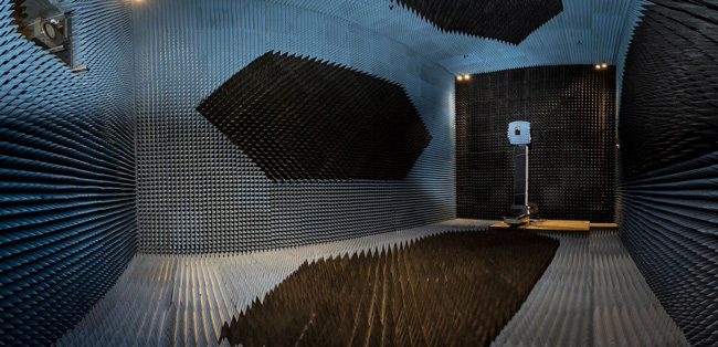
Figure 3 RFSTF mmwave chamber with horn AUT.
To achieve good RF performance up to 100 GHz, the central portions of the mmwave chamber walls, floor and ceiling are covered with unpainted 30.48 cm pyramidal absorber. Outside the central region, a blue-painted 20.32 cm pyramidal absorber is used. The AUT positioner is a polarization-over-elevation positioner mounted on a tower attached to a 0.61 m manual linear slide along the boresight axis over an azimuth positioner, which is the same configuration used in the RFSTF tapered chamber. The AUT positioner is optically aligned to facilitate accurate measurements of mmwave antennas. A tracking laser interferometer was used in the optical alignment process to align the lower azimuth, slide, elevation and polarization positioners. To maintain a fully shielded chamber, the source antenna horn is located in a shielded metal box with the open end facing the AUT. The source antenna is accessed from the control room and its position is adjusted in range and height with a dual-slide mechanism.
IV. SMALL NEAR-FIELD SCANNER
In the small near-field chamber, a 1.52 m by 1.52 m vertical planar near-field scanner (Nearfield Systems, Inc.) is typically used to calibrate and measure gain radiation patterns of small phased array aperture antennas. The scanner has a four-axis automated control for x, y, z Cartesian coordinates and probe polarization for vertical and horizontal polarization measurements. The scanner is in a shielded anechoic chamber with interior dimensions of 3.7 by 3.7 by 3.7 m, with the walls, floor and ceiling covered with 30.5 cm pyramidal absorber. Figure 4 is a photograph of a rectangular waveguide probe positioned in front of an S-band phased array of dual-polarized square patch antennas.
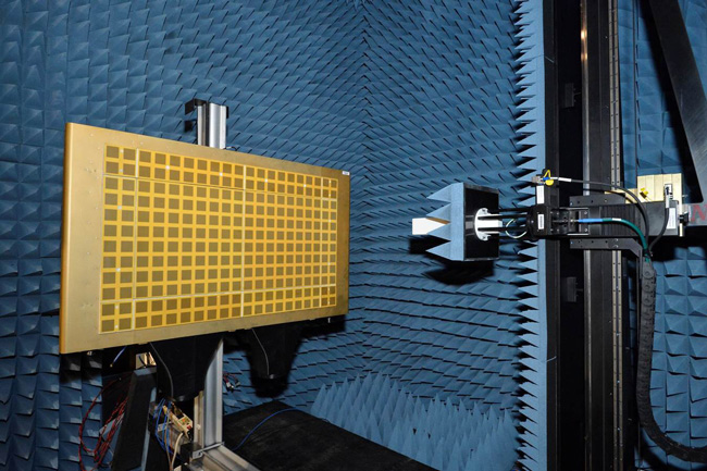
Figure 4 RFSTF small near-field scanner chamber with S-band dual-polarized phased array microstrip patch antenna panel under test.3
The probe antenna and vertical planar Cartesian coordinate scanner are surrounded by pyramidal absorber. The probe moves parallel to the array face, horizontally in the x direction and vertically in the y direction; and it moves perpendicular to the array face in the z direction as well. The rectangular probe shown is linearly polarized and is rotated by means of a polarization positioner to measure the voltage response to horizontal and vertical electric-field components for the AUT. The radiation pattern of the near-field probe with surrounding absorber is pre-measured and used to compensate and generate the far-field radiation pattern of the AUT. The antenna positioner in this chamber is also designed to rotate in azimuth to allow cylindrical near-field scanning. In this case, the probe scanner moves the near-field probe in the y direction and the AUT is rotated in the azimuth angle φ.
V. SYSTEM TEST CHAMBER
The general-purpose rectangular System Test Chamber, shown in Figure 5, is 18.3 m long by 12.2 m wide by 10.7 m high. It is RF shielded and covered uniformly with 1.22 m pyramidal absorber for RF testing typically from 150 MHz to 20 GHz. This chamber is used, in part, for standard far-field antenna testing and spherical near-field testing using an MI Technologies control and software system. A dipole array AUT and source antenna tower are also shown in Figure 5. The AUT positioner consists of an azimuth over elevation positioner on a tower mounted on a manual linear slide above a lower azimuth positioner over an automatic linear slide. The source tower is a linear positioner with a lifting capacity of 385 kg and has a polarization positioner with a DC to 26.5 GHz rotary joint.
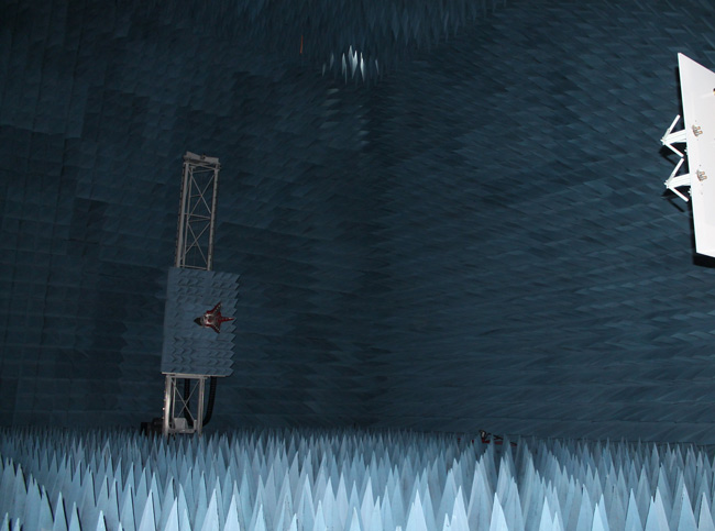
Figure 5 System Test Chamber with source tower and dipole array AUT.
To achieve accurate spherical near-field measurements, the coordinate systems of the source positioner and AUT positioner are laser aligned. The RF measurements system includes a 16-channel 0.1 to 20 GHz SP16T switch (multiplexer) that is used to collect measured AUT data from multiple antenna elements or from subarrays.
The facility is designed so that ground vehicles can be driven into the chamber for RF electromagnetic interference (EMI) testing and other RF measurements (see Figure 6). Pipe penetrations through one of the chamber walls are provided to allow vehicle exhaust gases to be removed from the anechoic chamber. The pipe penetrations can be closed to maintain full chamber RF shielding when not in use. Additionally, air vehicles (see Figure 7)6 or other test articles such as large radome panels (see Figure 8) can be suspended from an overhead crane for various RF measurements. For insertion loss measurements, the radome panel is first suspended well above the transmit and receive horns and then a baseline S21 measurement is made. The radome panel is then lowered between the two horns and relative insertion loss is then measured.
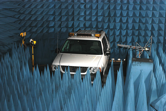
Figure 6 EMI testing in the system test chamber.3
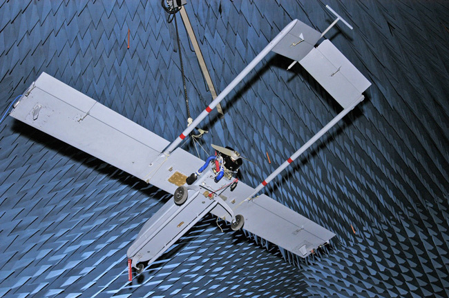
Figure 7 Air vehicle with belly-mounted ultrawideband VHF/UHF dipole array antenna and tail-mounted dipole suspended from the overhead crane during RF mutual coupling measurements in the system test chamber.6
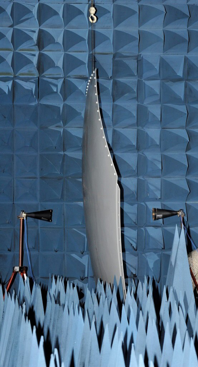
Figure 8 Radome panel insertion loss measurements setup at C-band utilizing the overhead crane in the system test chamber.3