
VI. ROLLED-EDGE COMPACT RANGE
The RFSTF compact range facility shown in Figure 9 has an EMI shielded anechoic chamber with interior dimensions of 20.1 m (length) by 13.4 m (width) by 11.6 m (height). The adjacent antenna/target handling room (antechamber) is 9.1 m long by 13.4 m wide by 11.6 m high. Electrically controlled large double doors provide a test article access opening 9.1 m high by 4.7 m wide. The anechoic chamber temperature is maintained in the range of approximately 20 to 22 °C to ensure a stable environment for maintaining the reflector surface shape and for RF stability of the chamber for RCS background subtraction.
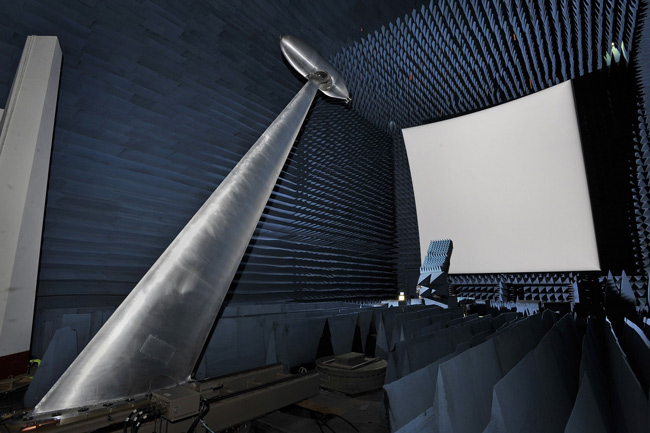
Figure 9 Compact range with low RCS ogive positioner.
The RFSTF compact range reflector antenna was designed by the Ohio State University and uses a blended rolled-edge design1-3, 7-10 to reduce diffraction from the edges of the reflector, which improves target zone amplitude and phase characteristics. The reflector is offset-fed to reduce feed blockage effects. Pulse gating is used to reduce multipath and further improve target zone characteristics. The rolled-edge parabolic reflector, feed and target support structures are located on a common isolated concrete slab to mitigate potential vibration effects. The walls, floor and ceiling of the chamber are covered with 0.91 m pyramidal absorber between the reflector and feed locations. From the feed to the back wall (behind the test article positioner), wedge absorber is used, varying in height from 0.9 to 1.1 m in a Chebyshev pattern.11, 12 The back wall is covered with pyramidal absorber in a Chebyshev pattern with absorber height varying from 0.91 to 1.1 m.
The offset-fed blended rolled-edge reflector antenna was provided by MI Technologies, 9, 10 and it is a composite structure with a projected aperture of 7.3 by 7.3 m. The reflector has a central parabolic section 3.048 by 3.048 m with a blended section to generate a 3.7 by 3.7 by 3.7 m quiet zone. The focal length of the offset parabolic reflector is 7.315 m. The electrically conductive surface of the reflector is a silver-based paint applied in multiple layers. The measured surface resistivity of the reflector is 0.11 ohms/square maximum over the surface of the reflector, which provides a highly electrically conductive surface. Reflector surface accuracy measurements were performed using a tracking laser interferometer.10
A gantry with a crane and scissors lift is used to move personnel, equipment and test objects to and from the test positioner. The crane has a lifting capacity of 1134 kg. The scissors lift has a lifting capacity of 454 kg for personnel and equipment. The gantry is electrically powered and rides on two rails recessed in the floor spaced approximately 4.1 m apart. Stairs next to the gantry allow personnel to access the gantry in the antechamber. A ladder is attached permanently to the gantry to allow additional access inside the test chamber.
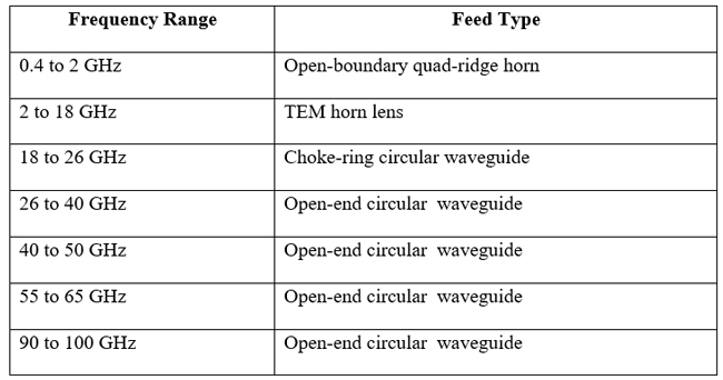
Seven dual linearly polarized feed antennas (see Figure 10) are used to illuminate the reflector in the frequency bands listed in Table I. The feed antennas are located on individual vertical slides on a platform that moves horizontally to allow the phase center of each horn to be placed at the focal point of the reflector. An absorber fence is placed behind the focal point feed location to reduce backlobe radiation from the feed into the target zone. A network analyzer-based signal source and receiver system with time gating, along with a 24-channel switch matrix, allows measurements of individual antenna elements in an array or of multiple subarrays for digital beamforming.
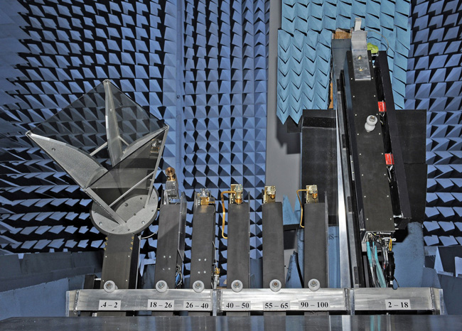
Figure 10 RFSTF compact range feeds. The 2 GHz to 18 GHz feed shown on the upper right has been moved up to the focal point of the reflector.
TABLE I
COMPACT RANGE DUAL-POLARIZED FEED ANTENNAS
The antenna positioner equipment normally used in this chamber is configured as follows: A lower azimuth over elevation positioner is located in a 1.37 m deep pit with a diameter of 3.35 m. On top of this positioner is a work platform and spacers upon which an automated 1.8 m linear slide is mounted above the floor absorber. The upper polarization-over-elevation positioner is mounted on a fiberglass tower that is attached to the linear slide.
Figure 11 shows an example of an ultrawideband dipole array panel under test in the compact range. Once this antenna panel measurement was completed, the panel and two others, were then mounted on the belly of an aircraft on the Lincoln Laboratory Flight Test Facility side of the hangar.3, 6 For radar cross section and some antenna measurements, the slide positioner, fiberglass tower, and upper positioner are removed using the gantry crane, and the lower azimuth over elevation positioner is used with one of a number of foam columns or the low RCS metal ogive (see Figure 9) to support and rotate test articles. The metal ogive mount has a roll axis stinger on top of an azimuth/elevation positioner.
Figure 12 shows a prototype inflatable dual-reflector antenna with feed horn under test on the ogive mount. This dual-reflector antenna is designed to be fed with a horn or with a phased array to provide limited electronic steering for space applications.13 Figure 13 shows an ultrawideband dipole array under test on one of the foam columns.6 In some cases during antenna or RCS testing on foam columns, the article under test can be secured with an electrically non-conducting tether (rope or harness) that is passed through a temporary hole/tube in the chamber ceiling, in which the tether is rigidly attached to structure above the chamber.
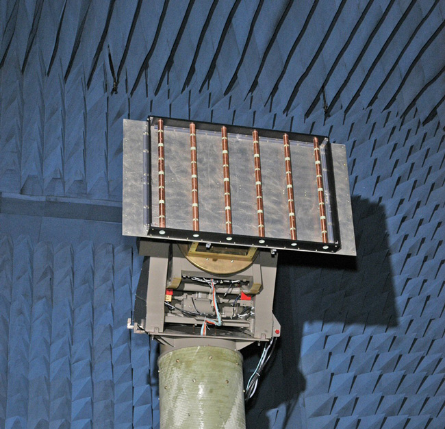
Figure 11 Ultrawideband dipole array panel under test on the compact range antenna positioner.3, 6
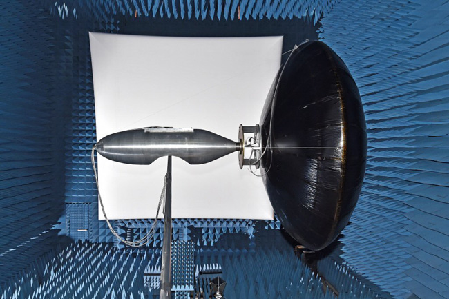
Figure 12 Compact range with 2.4 m diameter inflatable dual-reflector antenna13 under test with an X-band feed horn on the ogive positioner.
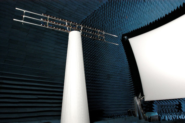
Figure 13 Compact range with ultrawideband UHF dipole array AUT on a foam column.6
VII. LARGE NEAR-FIELD SCANNER
In the large near-field chamber, an Orbit/FR 5.5 by 5.5 m vertical planar near-field scanner is used to calibrate and measure gain radiation patterns of large phased array aperture antennas. Operation of this large scanner is similar to the small near-field scanner described in the previous section. The scanner has four-axis automated control for x, y, z Cartesian coordinates and probe polarization (vertical and horizontal polarization measurements). The anechoic chamber interior dimensions are approximately 9.1 m (length) by 8.2 m (width) by 7.6 m (height). An overhead crane installed in the chamber has a lifting capacity of 3,629 kg (8,000 pounds). The walls, floor, and ceiling are covered with 46 cm pyramidal absorber with unpainted tips. The scanner is optically aligned and designed to perform accurate scans with multiple near-field probes from about 400 MHz to 50 GHz. An antenna assembly area with overhead crane is located adjacent to the anechoic chamber. The test antenna is moved into and out of the chamber on a general-purpose wheeled cart mounted on rails.
An example of a large phased array antenna setup for RF measurements is shown in Figure 14. The near-field probe is moved in front of each antenna element and the element phase shifters are cycled through their states, to provide a phase calibration look up table followed by offline processing for far-field radiation patterns.14-16 A standard gain reference horn mounted near the upper left of the array aperture is used to provide accurate gain measurements.
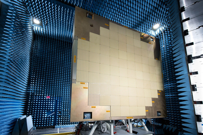
Figure 14 RFSTF large near-field scanner chamber with S-band multifunction phased array radar antenna.14- 16
VIII. RAPID PROTOTYPING SHOP, RF LABORATORY, AND SIL
The rapid prototyping shop (see Figure 15) has a wide variety of machining tools and 3D printers to fabricate antennas, target-mounting fixtures, and other mechanical pieces necessary to aid and assist in development of new hardware and testing in the facility. The prototyping shop is located in a high-bay area with a large capacity overhead crane, allowing for a wide range of mechanical work to be performed on larger devices and systems. The RF Laboratory (see Figure 16) and SIL (see Figure 17) are general-purpose areas that can be configured to support the needs of many different projects including RF assembly and test as well as development of advanced signal processing techniques and algorithms. The SIL will typically contain racks with transmitters and receivers and is directly connected to the System Test Chamber through a cable trough system allowing transmit and receive signals to be passed to and from the AUT.
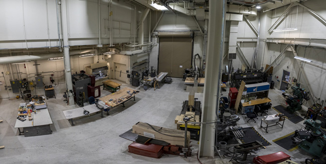
Figure 15 RFSTF rapid prototyping shop.
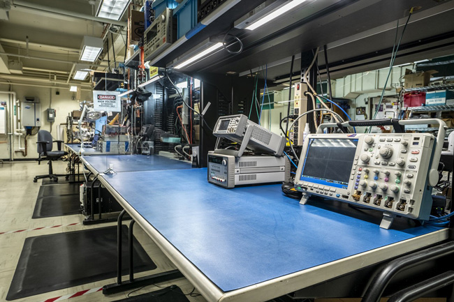
Figure 16 RF Laboratory at the RF Systems Test Facility.
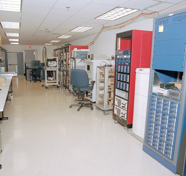
Figure 17 Reconfigurable SIL, which is connected to the System Test Chamber for radar, communications and other electromagnetic systems testing.
IX. SUMMARY
The RF Systems Test Facility at MIT Lincoln Laboratory provides rapid prototyping and RF measurements capabilities for numerous types of antennas, radar targets and electromagnetic systems.17 The facility has six shielded anechoic chambers consisting of a low frequency tapered chamber, mmwave chamber, small near-field scanner, system test chamber, compact range and large near-field scanner. The on-site machine shop, RF lab and system integration lab have significant roles in the rapid prototyping process at the RFSTF.
ACKNOWLEDGMENT
Technical discussions with Jeffrey S. Herd, Michael W. Shields, Paul A. Theophelakes, Edward D. Martin, M. David Conway, and Alexander F. Morris are sincerely appreciated.
This material is based on work supported by the United States Air Force under Air Force Contract No. FA8702-15-D-0001. Any opinions, findings, conclusions or recommendations expressed in this material are those of the author and do not necessarily reflect the views of the United States Air Force.
References
- A .J. Fenn, M. W. Shields and G. A. Somers, “Introduction to the New MIT Lincoln Laboratory Suite of Ranges,” 26th Annual Antenna Measurement Techniques Association Meeting & Symposium, October 2004.
- M. W. Shields and A. J. Fenn, “A New Compact Range Facility for Antenna and Radar Target Measurements,” Lincoln Laboratory Journal, Vol. 16, No. 2, 2007, pp. 381–391.
- A. J. Fenn, Electromagnetics and Antenna Technology, Artech, Boston, 2018, Chapter 12, pp. 428-444.
- K. H. Lee, C. C. Chen and R. Lee, “Update on UWB Dual-Polarized Tapered Chamber Feed Development,” Antenna Measurements Techniques Association Meeting, Stone Mountain, October 2004.
- A. J. Fenn, D. J. Pippin, C. M. Lamb, F. G. Willwerth, H. M. Aumann and J. P. Doane, “3D Printed Conformal Array Antenna: Simulations and Measurements,” IEEE International Symposium on Phased Array Systems and Technology, October 2016.
- A .J. Fenn and P. T. Hurst, Ultrawideband Phased Array Antenna Technology for Sensing and Communications Systems, Cambridge, MA: The MIT Press, 2015.
- I. J. Gupta, K. P. Ericksen and W. D. Burnside, “A Method to Design Blended Rolled Edges for Compact Range Reflectors,” IEEE Transactions on Antennas and Propagation, Vol. 39, No. 6, June 1990, pp. 853-861.
- T. H. Lee, and W. D. Burnside, “Performance Trade-off Between Serrated Edge and Blended Rolled Edge Compact Range Reflectors,” IEEE Transactions on Antennas and Propagation, Vol. 44, No. 1, January 1996, pp. 87–96.
- T. H. Lee, W. D. Burnside and I. J. Gupta, “Blended Rolled Edge Reflector Design for the New Compact Range at MIT Lincoln Laboratory,” Antenna Measurements Techniques Association Meeting, October 2004.
- J. R. Proctor, D. R. Smith, P F. Martin, G. A. Somers, M. W. Shields and A.J. Fenn, “Compact Range Rolled Edge Reflector Design, Fabrication, Installation and Mechanical Qualification,” Antenna Measurements Techniques Association Meeting, October 2004.
- R. Silz, “Design of the GE Aircraft Engine Compact Range Facility,” IEEE International Antennas and Propagation Society Symposium Digest, Vol. 4, July 2001, pp. 432-435.
- J. -R. J. Gau, W. D. Burnside, and M. Gilreath, “Chebyshev Multilevel Absorber Design Concept,” IEEE Transactions on Antennas and Propagation, Vol. 45, No. 8, August 1997, pp. 1286-1293.
- A. J. Fenn, J. H. Mills, F. C. Robey, P. Dufilie and M.H. Hecht, “Axisymmetric Gregorian Reflector System for a Space-Deployed Inflatable Antenna: Simulations and Measurements,” IEEE International Symposium on Phased Array Systems & Technology, October 2019.
- M. D. Conway, D. D. Russel, A. Morris and C. Parry, “Multifunction Phased Array Radar Advanced Technology Demonstrator Nearfield Test Results,” IEEE Radar Conference, April 2018, pp. 1412-1415.
- E. Kowalski, D. Conway, A. Morris and C. Parry, “Multifunction Phased Array Radar Advanced Technology Demonstrator (MPAR ATD) Nearfield Testing and Fielding,” IEEE Radar Conference, April 2019.
- J. S. Herd and M. D. Conway, “The Evolution to Modern Phased Array Architectures,” Proceedings of the IEEE, Vol. 104, No. 3, March 2016, pp. 519-529.
- A.J. Fenn, “Welcome to MIT Lincoln Laboratory’s RF Systems Test Facility.” Web. https://www.ll.mit.edu/sites/default/files/page/doc/2020-08/520612_Fenn_RF_Booklet-Marketing-on-Front-and-Back-Covers-ajf-17july2020.pdf, Accessed 2 November 2020.