
HAPS LINK CHARACTERISTICS
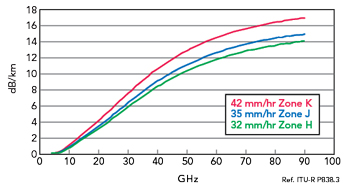
Figure 4 Rain attenuation per kilometer versus frequency for different ITU rainfall zones.
Breaking the converged network down into its individual elements, the characteristics that will be required for each of the links between them can be examined. Rain attenuation is one of the key factors to consider. Looking more closely at the HAPS feeder link geometry in Figure 2, for a platform at 20 km of altitude, the footprint can reach 70 to 80 km in diameter, and the link length will typically be about 40 km at an elevation of 30 degrees. Figure 4 shows the maximum rain attenuation per kilometer against frequency to permit 99.99 percent availability. For most of North America and Europe (Zone K), where rainfall is around 42 mm/hour, attenuation at 16 to 17 dB/km in E-Band is significantly higher than for the currently-used bands below 50 GHz. Nevertheless, as this service will be targeted at areas that have previously had no coverage at all, the demand for availability is likely to be lower than the 99.9 percent or 99.99 percent that is demanded of terrestrial networks, so some outage due to rain attenuation can be tolerated.
Potential data rates for HAPS feeder links in the different frequency band allocations are shown in Table 1, where they are compared for 256QAM and QPSK. Since antenna sizes are smaller at the higher frequencies, fade margins at 48 and 86 GHz are similar for the same antenna size and channel bandwidth. It is also striking that the data rate of over 10 GB/s that is available at E-Band using 256QAM is substantially higher than for the lower bands, due to the higher available channel bandwidth. Even if forced to drop back to QPSK to improve the fade margin, 2.5 GB/s data rate can still be achieved. The key figures for comparison are highlighted. Availability could be improved by combining E-Band with either 31 or 39.5 GHz.
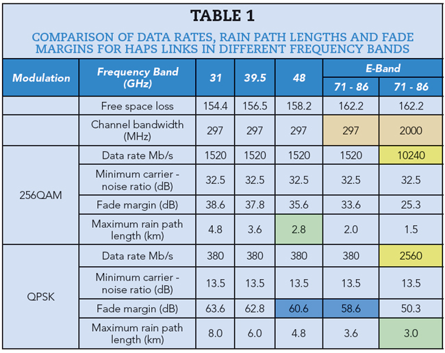
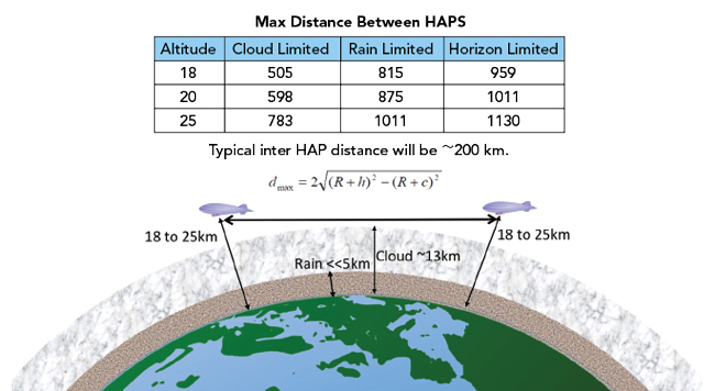
Figure 5 Distance limitations for inter-HAPS links.
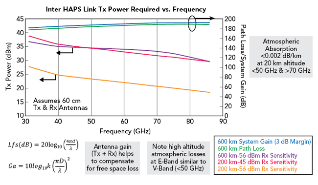
Figure 6 Transmitter power requirements for inter-HAPS links.
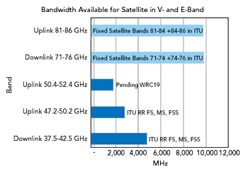
Figure 7a LEO satellite feed link bands.
Figure 5 shows the formula for calculating the maximum distance between HAPS, showing the distances calculated for the different limitations. The distance normally used between HAPS is around 200 km. Rain and clouds have far less effect when the platforms are at this altitude, and the greatest limitation is the curvature of the earth’s surface. Figure 6 shows the transmitter power that would be required for inter-HAPS links in the different frequency bands, indicating that high-altitude atmospheric losses at E-Band are very similar to those in V-Band below 50 GHz. The higher antenna gain for a particular size helps to compensate for free space loss.
SATELLITE LINK LIMITATIONS
Performing a similar analysis of the limitations on the feeder links for LEO satellites, Figure 7 shows the bands available and the geometry calculations involved. The orbits being used for SpaceX satellites are in the range of 350 to 1,100 km, and with an elevation of 35 degrees at the earth station this gives a link path length of between 600 and 1,700 km. Free space losses now become much more significant in comparison to atmospheric losses, as a higher proportion of the path is above the atmosphere. The free space loss is several tens of dB higher than the figures for HAPS feeder links - around 195 dB for a 1,700 km link length at 86 GHz.
When this is translated into system requirements, system gains between 180 and 200 dB are viable for mmWave satellite feed links in clear weather conditions, and this is achievable in E-Band with antenna gains of less than 58 dBi (equivalent to a 1 m parabolic antenna) and transmit powers less than +40 dBm. However, rain is a severe issue that can limit availability in both E-Band and V-Band, where increases in system gain of between 20 and 40 dB would be required to ensure acceptable availability. Inter-satellite links have no atmospheric limitations and fewer horizon issues, so LEOs can be many hundreds of kilometers apart.
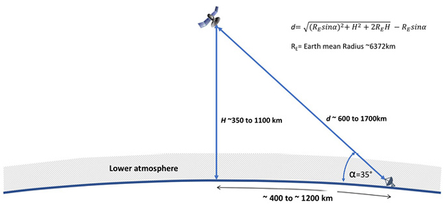
Figure 7b LEO satellite geometry.
Avoiding rain attenuation in feeder links is possible by using a mesh network that combines HAPS and satellites to form a resilient network, as shown in Figure 8. Thus, if a platform in a certain area is subject to rain attenuation, then the signal can be routed using software-defined networking technology via a different path to avoid the region that is affected by the storm.
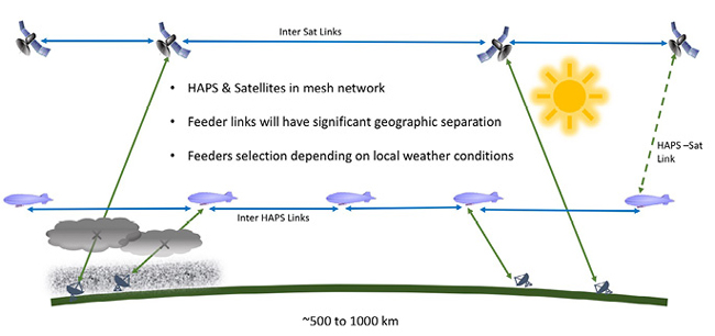
Figure 8 Mesh network combining HAPS and LEO satellites to avoid rain attenuation in feeder links.
MMIC TECHNOLOGY AND ACTIVE ANTENNAS
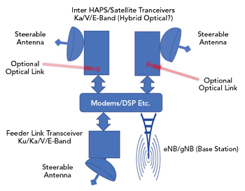
Figure 9 HAPS/satellite payload.
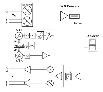
Figure 10 Block diagram of basic E-Band transceiver.
Although many power amplifier technologies at microwave frequencies now use GaN technology for better efficiency and higher power, it is rare to find GaN devices that work in V- or E-Band. Some experimental GaN devices have shown promising results up to around 100 GHz, but have not been commercialized yet, and it is challenging to find commercially available GaN devices above 40 GHz. Also, although SiGe and CMOS devices can work at the higher frequencies, their power levels are low, and many more elements would be needed to reach the required EIRP of around +60 dBm.
While phased array and active antenna technology has proved effective at increasing the gain and EIRP of antennas, as well as providing beam-steering, as the frequency increases the half-wavelength dimension becomes smaller and they become difficult to fabricate. Increasing the number of elements also increases power consumption, so using high-power GaAs devices with fewer elements has become the optimum solution for E-Band links.
E-BAND TRANSCEIVER TECHNOLOGY
Figure 9 shows a typical payload for a satellite or HAPS. As well as the eNodeB (LTE) or gNodeB (5G) base station, there are transceivers for the inter-platform links and the ground link, meaning that each platform would require three links at Ka-, V- or E-Band.
Figure 10 shows a block diagram of the basic transceiver that is being used for these E-Band links. It is fully integrated, for use in the 71 to 76 GHz and 81 to 86 GHz bands. It gives a highly linear transmitter output of more than 20 dBm and supports 256QAM modulation and above, along with a channel bandwidth more than 2 GHz. Phase noise is typically -112 dBc/Hz at 1 MHz. An integrated diplexer facilitates a single T/R port for the antenna interface, and there is also a single 50-way connector that supplies all communication between the module and the modem, as well as DC power, baseband data and control signals. A small, lightweight form factor is required, due to the number of elements to be accommodated and to optimize the overall weight of the payload. Morpheus II transceivers have a footprint of 90 × 80 mm and weigh only 110 g. For higher power levels, power combined amplifiers can be used - for example the Filtronic E-Band Cerus power amplifier can deliver output powers greater than 2 W. Figure 11 shows an example transceiver module, which is being used in E-Band links for terrestrial applications and has also been customized for HAPS/LEO links.
CONCLUSION
Global mobile data usage is growing rapidly, and the new use cases enabled by 5G will create demand in areas that are underserved - and difficult to serve - by terrestrial cellular networks, such as more remote and sparsely-populated regions. Terrestrial networks will not be able to provide 100 percent coverage, and this creates a clear case for converged networks that will integrate satellites and HAPS with terrestrial mobile networks. Although hybrid satellite solutions are not expected before 2023 to 2024, the standardization work for integration of the satellite in 5G networks is underway. Following the finalization of 3GPP Release 16 at the end of 2019, it is expected that provisions for satellite and HAPS systems could form part of Release 17. Since spectrum is limited and is subject to many conflicting and sometimes overlapping demands, mmWave frequency bands are expected to form a key part of the solution for the links between satellites, HAPS and earth terminals. The FCC has approved several trials in V-, E- and W-Bands, confirming the growing role for mmWave bands in the future.
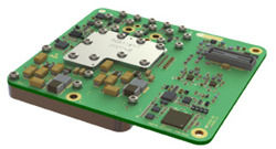
Figure 11 Filtronic Morpheus II E-Band transceiver.
While the use of mmWave bands presents some technological challenges for semiconductor devices, RF systems, antennas and network architectures, some long range mmWave transceiver solutions with high data rates up to 40 Gb/s and above have been developed and successfully demonstrated in trial systems and will improve for future systems.
For more information on this material, visit YouTube at
https://youtu.be/bDGmkIF4-no.
Reference
1. D’Oliveira et al., “High-Altitude Platforms - Present Situation and Technology Trends,” Journal of Aerospace Technology and Management, Vol. 8, No. 3, 2016, www.jatm.com.br/ojs/index.php/jatm/article/view/699.
*In late January 2021, Alphabet/Google decided to shut down Loon -
https://www.reuters.com/article/us-alphabet-loon/alphabet-shutting-loon-which-used-balloon-alternative-to-cell-towers-idUSKBN29R02U