
With the steady improvements in tracking radar technologies over the past twenty years, the diameter requirements for antennas has been reduced to match the improvements in transmitter power and receiver sensitivity. This has led to a need for shorter feeds for use in Cassegrain configurations.
Antenna feeds have recently been developed for use at C-band, which are fabricated from cast waveguide components and optimized to tight phase characteristics. As a long-standing manufacturer of monopulse comparators, the development of an antenna feed was the next logical step in the extension of the product range. The choice of horn design was crucial to achieving a compact feed design.
The first C-band feed was developed for a nine-foot reflector and used a four-horn arrangement directly on the outputs of the comparator. This gave a small footprint to the feed that reduced blockage of the main reflector; however, the beamwidths in the elevation and azimuth difference patterns were excessive, resulting in high sidelobe levels.
The next generation feeds incorporated two auxiliary horns each in both the azimuth and elevation planes resulting in an eight-horn design. The sum pattern was unaffected by the new arrangement and gave similar performance to the earlier design. The delta patterns were significantly narrower giving reduced sidelobe levels, even though the footprint was increased.
The company's compact comparator uses four waveguide tees connected via four extension waveguides to the central four horns. The overall waveguide section is tuned to achieve less than ±1° phase imbalance between ports. The C-band version is capable of handling up to 1MW peak power at normal atmospheric pressure. It is designed for operation up to 30 PSIA, and should be pressurized to maintain a dry atmosphere inside the waveguide.
Sum, elevation and azimuth ports are provided as waveguide flanged interfaces. Isolation between any two ports is 35 dB minimum. When fitted to an antenna, cross polarization ratios of 30 dB minimum and an error channel null stability of less than 0.1 mil across the frequency range are achieved.
The auxiliary horns are connected to a power combiner network that includes the tees that are part of the central comparator. The two horizontal horns are combined with the azimuth signal from the comparator while the two vertical horns are combined with the elevation signal. All the interconnecting waveguide are phase matched during manufacture. A final test in an anechoic chamber allows the beam patterns from the main and auxiliary horns to be set coincident, thus providing accurate combining to give the maximum possible null depth. When fitted to an antenna, null depths of 35 dB minimum are achieved with typical values greater than 50 dB.
The first eight-horn feeds used coaxial cables to connect the auxiliary horns to the power combiners. This resulted in a very compact feed, especially in the version fitted to the eight-foot reflectors, as shown in Figure 1 . Further development has replaced the cables with waveguides, which, in addition to providing lower insertion loss, also provide better protection against the environment. Although the earlier feeds were exclusively for C-band operation, versions have been developed for X-band using the company's range of precision investment castings.

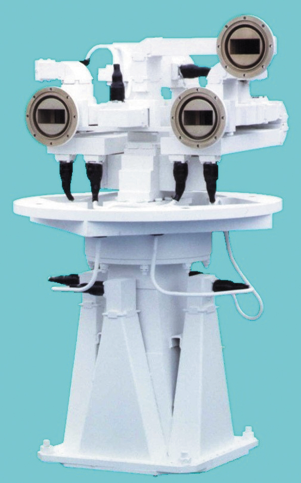
Compared to a multimode horn the eight-horn array is much shorter in overall length. This allows the C-band version to be fitted in antennas with reflector diameters down to eight feet, without the comparator protruding far behind the dish. When fitted into a 12- or 16-foot reflector, as shown in Figure 2 , extension waveguides are fitted to increase the overall feed length. These are used to improve the phase balance of the comparator, resulting in improved antenna performance.
Micro Metalsmiths Ltd.,
Pickering, N. Yorks, UK
+44 1751 475058.
Circle No. 303