
Antenna Array Scan Properties
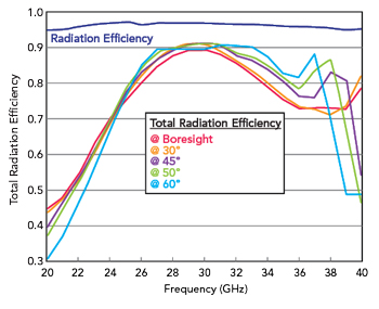
Figure 5 Total radiation efficiency of the 8x8 DRA array shown in Figure 4 as a function of scan angles and frequency along the H-plane.
The aperture-fed DRA detailed in the previous section is placed in a uniform 64-element array consisting of 8x8 elements, as shown in Figure 4. The inter-element spacing is about half-wavelength at 28 GHz. The objective is to examine the array performance while beam steering over the operational range of frequencies.
For a two-dimensional planar array, the beam steering angle (θ, φ) can be controlled by setting certain phase values at the (m, n)th port according to Equation 1, in which m and n stand for row and column, dx and dy stand for the spacing in x- and y- direction, respectively.9

As shown in Figure 5, the phased DRA array features wideband characteristics. The total radiation efficiency is better than 80 percent over the frequency band between 26 and 34 GHz along the H-plane. Also, the DRA array displays nearly flat efficiency characteristics over a wide scan range. Such high performance is related to the fact the DRA radiating elements are wideband and the electromagnetic field is confined within the relevant dielectric rod. As a result, the inter-element coupling is much smaller as compared to patch array antennas. A comparable patch array antenna with equivalent aperture and inter-element spacing displays a much narrower band performance with a poor efficiency away from the central resonant frequency, as it appears from Figure 6. The patch array elements are fed via slots. The dielectric laminate on which the patch antenna elements are printed is RO4308 with relative permittivity of εr = 3.6.

Figure 6 Total radiation efficiency of a patch array antenna as a function of frequency and scan angle.
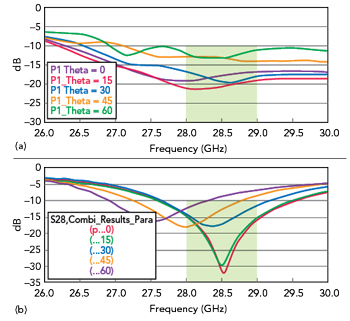
Figure 7 Frequency-domain behavior of the magnitude of the active input reflection coefficient displayed by an 8x8 array of DRA (a) and patch antennas (b) for φ = 0° and ϑ = 0°, 15°, 30°, 45°, 60°.
The active reflection coefficient of the array is significantly more complicated to evaluate as it requires the evaluation of the mutual coupling data between the activated array element and the adjacent elements. Based on the derivation in Pozar,7 for a two-dimensional planar array, the active reflection coefficient Γ can be calculated by Equation 2, where Sm,n stands for the mutual coupling coefficient between the m-th and n-th ports. As shown in Figure 7, the broadband characteristics of the proposed DRA array, as compared to the equivalent structure based on patch antenna elements, are also validated in active mode, that is while beam scanning. The considered array structures feature equivalent inter-element spacing and aperture.

In Figure 8, the scan-loss characteristics along both the H- and E-plane are evaluated. From the obtained results, it can be inferred that the scan loss along the H-plane follows the array factor of an ideal cosine source. The performance is just slightly degraded along the E-plane. This difference is mainly due to the asymmetry of the average embedded pattern of the array. On the other hand, a significant advantage is related to the fact that the array performance is stable over a very large frequency band.
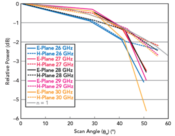
Figure 8 Beam steering scan loss displayed by the 8x8 DRA array with scan loss evaluated as a function of frequency along the relevant E- and H-planes.
As it appears in Figure 9, the proposed DRA array displays robust performance also against manufacturing tolerances related to the misalignment or misplacement of the radiating structure on the circuit board containing the relevant feeding network. This is important to ensure reduced sensitivity of the array to non-idealities typically encountered in mass-production assembly lines.
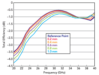
Figure 9 Total efficiency of the 8x8 DRA array as a function of the misplacement of the radiating structure on the circuit board containing the relevant feeding network.
CONCLUSION
The antenna impedance bandwidth can be easily tuned in such a way to synthesize a wide- or multi-band frequency response by the combination of DRAs and radiating slots. The proposed DRA array achieves a total radiation efficiency better than 80 percent in the band from 26 to 34 GHz and large scanning angles compared to a conventional half-wavelength spaced patch antenna array. With the advances in material science and manufacturing techniques, DRA technology can become a cost-effective, high performance solution for 5G wireless communications.
References
- IEEE 5G, “IEEE 5G and Beyond Technology Roadmap White Paper,” 2017, https://futurenetworks.ieee.org/images/files/pdf/ieee-5g-roadmap-white-paper.pdf.
- K. W. Leung, E. H. Lim and X. S. Fang, “Dielectric Resonator Antennas: From the Basic to the Aesthetic,” Proceedings of the IEEE, Vol. 100, No. 7, 2012, pp. 2181–2193.
- A. Petosa and A. Ittipiboon, “Dielectric Resonator Antennas: A Historical Review and the Current State of the Art,” IEEE Antennas and Propagation Magazine, Vol. 52, No. 5, October 2010, pp. 91–116, http://ieeexplore.ieee.org/document/5687510/.
- S. A. Long, M. W. McAllister and L. C. Shen, “The Resonant Cylindrical Dielectric Cavity Antenna,” IEEE Transactions on Antennas and Propagation, Vol. 31, No. 3, 1983, pp. 406–412.
- S. Keyrouz and D. Caratelli, “Dielectric Resonator Antennas: Basic Concepts, Design Guidelines, and Recent Developments at Millimeter-Wave Frequencies,” International Journal of Antennas and Propagation, Vol. 2016, pp. 1–20, www.hindawi.com/journals/ijap/2016/6075680/.
- M. Simeoni, R. Cicchetti, A. Yarovoy and D. Caratelli, “Plastic-Based Supershaped Dielectric Resonator Antennas for Wide-Band Applications,” IEEE Transactions on Antennas and Propagation, Vol. 59, No. 12, December 2011, pp. 4820–4825.
- D. M. Pozar, “The Active Element Pattern,” IEEE Transactions on Antennas and Propagation, Vol. 42, No. 8, August 1994, pp. 1176–1178.