
Leveraging years of experience, the Advanced Radar Research Center (ARRC) at the University of Oklahoma (OU) is building the first-ever, mobile polarimetric, all-digital phased array radar (PAR),1 as depicted in Figure 1. As technology has significantly evolved over the last 10 to 15 years, especially in the areas of analog-to-digital converters (ADC), digital-to-analog converters (DAC), high-power amplifiers and field-programmable gate arrays (FPGA), the possibility of moving significant portions of a radar system closer to the aperture of a phased array antenna has become a reality. Figure 2 depicts the overarching architecture of the all-digital PAR system, wherein an independent digital receiver and digital transmitter exist for each horizontal (H) and vertical (V) channel for each of our dual-pol elements.
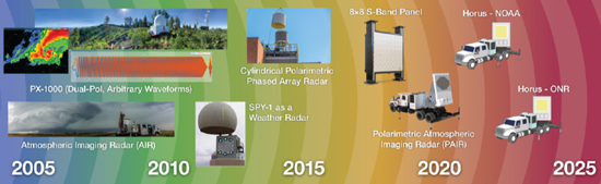
Figure 1 Genesis of the ARRC’s mobile polarimetric all-digital phased array radar development.
RADAR EVOLUTION
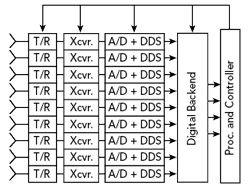
Figure 2 An independent digital receiver and digital transmitter exist for each element.
Over the last 15 years, the ARRC has been engaged in the national Multifunction Phased Array Radar (MPAR) initiative, and subsequently the Spectrum Efficient National Surveillance Radar (SENSR) Program, as initially coordinated by the Federal Aviation Administration (FAA), Department of Defense (DoD), Department of Homeland Security (DHS) and National Oceanic and Atmospheric Administration (NOAA). Consequently, the ARRC is developing a scalable all-digital polarimetric S-Band phased array that addresses the requirements for weather and long-range aircraft scanning. The array will also support other important modes of operation including MIMO and general communications.
Agile beam steering and multifunction capabilities now make phased arrays the best candidates for multi-mission radar systems, offering efficient and cost-effective solutions. Advancements in GaAs, SiGe, CMOS and GaN technology provide reliable, highly integrated and affordable RF components that have enabled phased array antennas to become a core technology for modern remote sensing and communication. High levels of integration and more efficient components have allowed for phased array antenna architectures with multiple transceivers that can be used to increase functionality and performance at reduced cost, size and weight compared to their predecessors that exclusively used analog beamformers: for instance, 5G will certainly leverage phased array technology. Arrays with analog beamforming are inherently constrained to the beamforming scheme imposed by the exact configuration of front-end beamforming electronics.
Presently, digital beamforming (DBF) at the sub-array level is a common approach to increase the flexibility of phased array radars, as demonstrated by the 76-panel Advanced Technology Demonstrator (ATD) operated by NOAA’s National Severe Storms Laboratory (NSSL) and the University of Massachusetts’ (UMass) Raytheon Low-Power Radar (i.e., Skyler). Yet, the move towards element-level DBF architectures offers unprecedented capabilities. Examples of such systems include; Australia’s CEA-FAR naval radar, the U.S. Navy’s FlexDAR radar,2 Israeli Elta’s MF-STAR, AFRL’s BEEMER (Baseband-digital at Every Element MIMO Experimental Radar) and Space Fence, to name a few. Moreover, digital at every element makes exquisite control of polarimetry a possibility, with single H, single V, simultaneous H&V for slant 45, LHC, RHC or arbitrary polarization states.
Digital array technology is a nascent research endeavor; a thrust of Combat Capabilities Development Command Army Research Laboratory’s (CCDC ARL) research is the development of robust techniques for array calibration. Operation in crowded and contested environments depends critically on protecting radar operations and maintaining calibration in dynamic environments. Factory calibration is insufficient for digital arrays, and methods for robust in-situ calibration are needed that are also computationally efficient. In conjunction with partners including OU and CCDC ARL is developing mutual coupling-based calibration techniques to address this problem. CCDC ARL is conducting proof-of-concept experiments to quantify performance of initial algorithms using an element-level digital array laboratory test asset. Moving forward, CCDC ARL will extend these techniques for wider bandwidth performance and focus on scalability to large-format arrays, as well as suitability for operational environments outside of the laboratory test bench.
FULLY DIGITAL ARCHITECTURE
Even though implementation of dual-polarization on PAR has proven challenging, significant progress has been made recently, as reported by a community workshop of radar technologies sponsored by the National Science Foundation (NSF),5 such as MIT Lincoln Lab’s S-Band panels at the ATD,6 BCI/LMCO’s S-Band prototype, NCAR’s C-Band airborne phased array radar system, UMass’ X-Band radar, and OU’s S-Band cylindrical polarimetric phased array radar (CPPAR) demonstrator.7 In order to improve the temporal resolution on spotlight operation, the single-polarized X-Band Atmospheric Imaging Radar (AIR) was developed by the ARRC several years ago, as shown in Figure 1. The AIR operates in a “floodlight” mode, utilizing a 20-degree vertical fan beam on transmit and 36 receiving arrays capable of fine scale digital beamforming. In other words, a range height indicator (RHI) of radar measurements can be formed simultaneously, similar to taking a picture with an electromagnetic camera. This configuration, combined with 20 degrees/sec mechanical scanning in azimuth, allows the current AIR to collect 180 by 20 degree volumes in approximately nine seconds; hence, the world’s highest resolution observations of tornado genesis.8 A similar system with floodlight operation is the X-Band PAR located at Osaka University.
These advanced imaging surveillance modes of operation require digitization of multiple subarray channels. Increased levels of digitization also enable adaptive digital beamforming (ADBF), space-time adaptive processing (STAP) and even MIMO modes of operation. An ideal phased array architecture would feature digitization and control of both the transmitted and received signals at each antenna element, along with the ability to cover wide bandwidths. Because the element-level processing and subsequent beamforming are digital, it can be reconfigured and optimized for different applications. Digitization at the element level opens the door to new processing and beamforming schemes and delivers maximum flexibility with unprecedented dynamic range in large systems. For instance, given M elements and uncorrelated noise at each element, the signal-to-noise ratio of the system is increased by 10log(M). However, this comes with inherent technological risks and practical challenges associated with the amount of data to process and the use of less sophisticated transceivers.
Figure 3 shows three example modes of our all-digital PAR system. The left panel of Figure 3 depicts several typical high sensitivity beams and several low priority beams, which are needed for continuously dwelling in an area to glean important information. The middle panel of Figure 3 depicts a space time multiplexing paradigm whereby sets of independent samples can be collected from a surveillance area; this allows data to be collected with fewer samples. Since adaptive spatial filtering can be achieved via a phased array,4 this greatly demonstrates the use of a phased array over a typical parabolic dish antenna. Finally, the right panel of Figure 3 depicts how our mobile demonstrator will leverage the team’s imaging expertise so that rapid volume scanning may be achieved.8
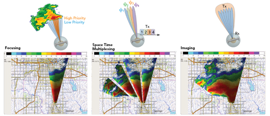
Figure 3 Three example radar modes that demonstrate the efficacy of an all-digital array.
For any future multi-mission radar, multiple interleaved functions are practically the only way to satisfy the bevy of mission requirements in a given timeline, so advanced beamforming flexibility through digitization is critical. Furthermore, additional missions over the lifetime of a digital PAR could be implemented with software upgrades, rather than costly hardware retrofits, resulting in significant operation and maintenance cost savings. The next section provides an overview of the development of an S-Band, dual-polarization PAR that is being designed and built at the ARRC that will achieve these goals. This system, which we call Horus, has a digital transceiver per polarization, per element and will be a valuable research tool in evaluating the benefits and challenges to such an approach.