
RF MEMS switches combine extremely low loss and high power-handling in a unique SP4T configuration, which enables the creation of miniaturized and very high performance switched filter banks (SFB).
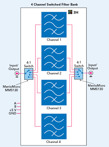
Figure 1 Block diagram of a 4-channel switched filter bank.
SFBs are becoming more and more common for both commercial and military applications with the proliferation of communications frequency bands and the deployment of more frequency-agile radios. Traditional SFBs that use semiconductor devices as the switching element to select discrete filters are increasingly preferred over their electromechanical counterparts. In some applications, however, the additional losses associated with semiconductor switches is prohibitive. This is problematic when considering that at least two switches are required, at both the input and output of the filter bank, which can drive losses from switching alone to 3 to 4 dB - or higher depending on the number of filter selections and the frequency range of operation. Such losses can create significant challenges for radio designers, especially in high-power applications where 3 dB corresponds to a significant amount of power dissipation (i.e., heat) that must be managed. Recently, RF MEMS switches have become available that combine extremely low loss and high power-handling capability in a unique SP4T configuration. This enables the creation of miniaturized and high performance SFBs. This article explores the underlying technology, design approach and resulting performance.
THE GROWING NEED
RF filters are some of the most mission critical components in any wireless communications system. Smaller and lighter weight RF filters are desired to meet the demand for smaller and more capable mobile wireless communication devices whether they are used in handheld radios such as cell phones; inside a drone, an airplane, a satellite; or even on mountaintop cell towers.
The degree of rejection needed from a filter is unique to each radio, whether it is to suppress spurs or mitigate interference. This creates the need for custom filters. The significant advantages of SFBs have resulted in their widespread use in diverse applications such as radar, electronic warfare, communications and test and measurement. SFBs combine switches and filters in a single module, where a switch at the input is followed by a filter for each channel and followed by a switch at the output (see Figure 1).
SFBs have significant benefits compared to approaches in which discrete switches and filters are used. The most obvious is less board space and the ease of using a single integrated module. The modules contain all or most of the components required to perform the switching function, including a microcontroller, power management and amplifiers (if required).

Figure 2 Switched filter bank use case.
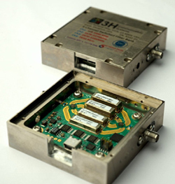
Figure 3 Four-channel switched filter bank with four lumped element filters and two SP4T MEMS switches.
An SFB also eliminates circuit transitions, which enables more precise impedance matching and lower insertion loss. Because the channels are internal to the module, better rejection and isolation are achieved. Any filter topology can be used based on the requirements of the application, including rejection, insertion loss and power handling.
In general, whether in the receive (Rx) or transmit (Tx) path, a key performance metric is insertion loss. To limit out-of-band interference, in receive, the SFB will usually be situated before any low noise amplifier; insertion loss from the SFB will contribute directly to the Rx system noise figure. In transmit, the SFB will be situated between the power amplifier (PA) and antenna to limit spurious and other interference from being radiated. Low insertion loss and high linearity are key to system performance; insertion loss determines radiated power, and linearity determines interference levels and receiver sensitivity. An example of a switched filter bank application is shown in Figure 2.