
Base station deployment and site acquisition constraints require smaller, lighter 5G massive MIMO (mMIMO) radios and antennas. Improved signal processing, high efficiency devices and integration from discrete lineups to front-end modules (FEM) make it possible.
The RF and microwave industry has made considerable progress toward enabling commercial sub-6 GHz 5G wireless infrastructure, with mmWave fixed wireless trials progressing in parallel. The early excitement surrounding 5G has given way to a defined set of industry standards, and component and system manufacturers have variously aligned on practical, scalable 5G base station architectures that deliver the promise of faster data throughput and expansive capacity to serve subscriber, IoT and other applications.
The evolution from 4G to 5G - and the anticipated 100x capacity improvement required by our ever-increasing demand for data - requires a fundamental change in cellular communication RF system architecture and design. With so many users, devices, automobiles, smart meters, low-power wide-area devices and other machine-to-machine communication, the capacity of 4G cellular systems employing fixed sector antenna systems will fall short. At the highest level of communication theory, it is well known that maximizing throughput over a wireless channel requires maximizing signal-to-noise ratios (SNR) or signal-to-interference+noise ratios (SINR). High density cellular networks are typically interference limited, not noise limited, forcing the RF architecture to evolve into a system where interference is managed. Here is where mMIMO systems come into the picture. mMIMO, with many more transceivers and antenna elements than are used in 4G systems, uses beamforming signal processing to direct RF energy to users and reduce interference by dynamically steering antenna beams away from interfering sources, in both azimuth and elevation. By steering RF energy to users and away from interference, SINR, throughput and overall system capacity improve.
mMIMO CHALLENGES
With 5G antenna array and mMIMO technology coming to fruition, wireless network operators will face deployment challenges as they make the transition from 4G LTE to 5G base stations, an incremental evolution that will see both technologies comingled for what is likely to be an extended period. Occupying similar physical footprints, 4G LTE and 5G base stations will, wherever possible, populate existing co-located cell towers and rooftop installations, configured as they are today to minimize interference and coverage gaps.
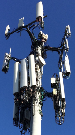
Figure 1 Typical cell tower installation, with two tiers of radios and antennas.
As 5G base stations proliferate across existing sites, available installation space will shrink dramatically, space that is already at a premium from continued 4G LTE base station deployments in some regions. Indeed, many cell towers have already been pushed to the brink of their hosting capacities, evidenced by the increasingly and chaotically-cluttered towers dotting today’s metro environments. Figure 1 shows a typical tower installation with two tiers of antennas, radios, RF cables and power feed lines, which represent approximately 250 kg weight on each sector. Wind loading, ice loading and moment arms are key factors as base stations multiply on a tower, with concern for base station resilience and service continuity in poor weather conditions.
These challenges must be met with smaller, denser sub-6 GHz 5G base station designs. In parallel, base station weight and volume remain critical considerations for system designers, given the nontrivial labor and equipment costs imposed on wireless operators for installation and subsequent maintenance. Where operating costs were calculated based on just the aperture size of the antenna, tower operators have largely moved to a pricing model where charges are calculated using base station weight, aperture area and volume. Initial installation costs are also determined by the location, weight and type of installation: tower or rooftop, one or two people, crane, etc. The initial 4G systems were split into a radio head and an antenna, where the radio was often on the ground and the passive antenna mounted on the tower. In other installations, both radio and antenna were located on the tower, with commensurate costs. 5G mMIMO antennas, by definition, will position the active electronics on the tower, immediately behind the antenna, in a single integrated unit.
Of course, base station size and weight have always and will always be central concerns for RF component providers, base station designers and operators. A looming shortage of tower and rooftop real estate will only exacerbate these problems. On the path to realizing commercial-scale mmWave 5G connectivity, site acquisition will become infinitely more difficult, given the 100 m spacing between base stations that frequency and physics require for uniform coverage. mmWave base station equipment installed on lamp posts, street signs, bus stop shelters and other structures will need to be far lighter and less obtrusive than anything that has come before.
Site acquisition challenges will be compounded by concerns over the effective isotropic radiated power (EIRP). While 4G LTE and sub-6 GHz 5G base stations may exhibit comparable EIRP levels when accounting for beamforming gain, increasingly higher frequencies will require higher RF power to compensate for building penetration losses and boost the EIRP to achieve comparable indoor coverage. Diffraction losses, aperture efficiencies and path loss all suffer as a function of frequency (i.e., 6 to 12 dB/octave), while penetration losses increase dramatically at higher frequencies due to the skin depth and conductivity of coated glass, conductive (moist) masonry, brick faces and other materials.
Health and safety requirements dictate that EIRP emission limits (1 mW/cm2) and exclusion zones remain within acceptable levels in the transition from 4G LTE to 5G, so raising EIRP levels will naturally introduce some placement challenges. These will be compounded with the implementation of mMIMO beamforming techniques if theoretical maximum power is used. Where conventional antennas point horizontally, beam steered antenna arrays will radiate in many directions, even down into pedestrian walkways. This health and safety concern will introduce additional constraints for acquiring urban 5G base station sites, intensifying the pressure to design smaller, lower power base stations that can be flexibly deployed while preserving safety.
REDUCING SIZE AND WEIGHT
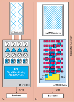
Figure 2 Architecture of a conventional 4T LTE remote radio head (a) vs. a mMIMO radio containing 192 antenna elements and 64 TRx FEMs (b).
When it comes to optimizing sub-6 GHz base station size and weight, several design considerations must be considered, from the component to the system, with power consumption, efficiency and thermal dissipation the most important.
Antenna aperture size is wholly dependent on the number of onboard antenna elements, which depends on the desired network capacity and expected interference. Whether the array has 64, 128 or 192 elements, the physical dimension is determined by the physics of the array, scanning angle requirements, grating lobe performance and beam widths. The volume and depth of the base station, determined by the underlying electronics and heat sinking, can absolutely be optimized; here, we see plenty of room for improvement.
A key system size consideration frequently overlooked with 5G mMIMO is the dramatic increase in signal processing hardware required, compared to typical LTE systems. The mMIMO system may have 192 antenna elements connected to 64 transmit/receive (TRx) FEMs with 16 transceiver RFICs and four digital front-ends (DFE), a 16x increase in digital signal processing compared to the four transceivers in a typical LTE 4T MIMO system (see Figure 2). Add a 5x increase in bandwidth when moving from 20 to 100 MHz, for example, and the signal processing multiplier is staggering. The stackup in Figure 3 illustrates the functions in a typical mMIMO integrated antenna and radio. The top panel contains the antenna elements, and the layers below the antenna contain the RF and digital circuitry. While the TRx FEM, RFIC and DFE layers are shown as separate boards, in practice the three functions will be combined into one or two densely packed boards to minimize interconnections.
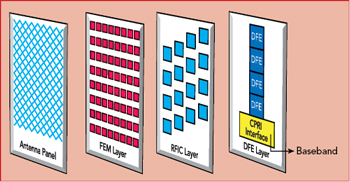
Figure 3 Notional mMIMO radio stackup.
Perhaps even more jarring than the additional hardware in a mMIMO system is the attendant impact on power consumption and heat dissipation. Previously, power amplifier (PA) power consumption was the most important factor when designing base station heat sinks and power supplies. Now, the power consumption of the signal processing electronics is approaching, and in some cases, eclipsing that of the onboard PAs.
The significant increase in signal processing hardware can be offset to an extent by optimizing the signal and waveform conditioning algorithms applied to the transmitted signals. Legacy signal conditioning algorithms such as crest factor reduction and digital predistortion (DPD) were primarily developed for macro base stations with very high-power PAs, a more complicated and taxing processing workload than is required for the smaller, lower power PAs populating mMIMO antennas. These algorithms easily consumed 75 percent of the available signal processing resources in the DFE processors, whether custom ASIC/SOCs or FPGAs. By streamlining these algorithms for 5G mMIMO architectures and redistributing the functionality across several logic blocks, a minimal set of optimized algorithms will improve signal processing efficiency, reducing overall power consumption.
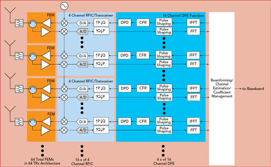
Figure 4 Typical mMIMO radio functional block diagram.
To illustrate the 16x multiplier of the digital signal processing and transceivers in a mMIMO system, a functional block diagram is shown in Figure 4. This architecture is typical of all mMIMO designs, with some differences in the partitioning of logic (e.g., 8- or 16-channel DFEs) or discrete component instead of integrated FEMs. This example shows, from left to right, 64 RF and transceiver paths divided among 16 transceiver RFICs driving four DFEs. The DFEs process the digital data from the 64 channels and are connected to the beamforming processor and baseband interface processor. The emergence of RF SOCs with direct sampling analog-to-digital converters (ADC) and digital-to-analog converters (DAC) capable of ~60 GSPS help to shrink the size and weight of 5G antennas by reducing the steps required for analog up- and down-conversion in conventional transceiver architectures. This reduces the overall component count and cost by eliminating mixers, converters and local oscillators.