
Terminology cont.
Return loss. Related to VSWR, return loss (in decibels) indicates the level of power reflected from a device due to a mismatch. With a perfect match between a transmission line and a load at its output, very little, if any, power is reflected, and the difference between the input level and the reflected power is a large number of decibels. If there is a short circuit or an open circuit at the output of the transmission line, all the incident power is reflected back, and there is very little difference in decibels between the two. It is important to understand that a much better match in a circuit (a more desirable condition) is represented by a higher value of return loss as well as a lower VSWR.
Reflection coefficient. The reflection coefficient is the ratio of the amplitude of the reflected wave to the incident wave at the end of a transmission line or at the input or output of a circuit. It is related to VSWR as well. The magnitude of this ratio squared and multiplied by 100 represents the percentage of power reflected from a mismatch. If there is a perfectly matched condition, the reflection coefficient is 0 (0 percent); if there is an open circuit or a short circuit at the end of a transmission line, the reflection coefficient is 1 (100 percent). Any mismatched condition between those two extremes is between 0 and 1. The designation for the reflection coefficient is either ρ or G, depending on the publication. A low reflection coefficient represents a good match. A high reflection coefficient is an indication of a large mismatch and, consequently, a high VSWR and low return loss.
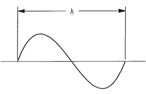
Figure 4 Wavelength definition.
Wavelength. A wavelength is the length of one cycle of a signal, as illustrated in Figure 4. Wavelength is designated by the symbol λ. One wavelength is the distance between two adjacent points with the same amplitude. If, for example, we measure 0.1 V at one point on the wave, one wavelength will be where the wave is 0.1 V again. Values commonly used in high frequency applications are λ/2 (half wavelength) and λ/4 (quarter wavelength).
Frequency. This simply means how many times an electromagnetic wave repeats itself (i.e completes one full cycle) in 1 second. One cycle per second is defined as 1 Hz. For example, 1 GHz means that the wave repeats itself 1,000 million times in 1 second (1 billion times per second).
Short circuit. For high-frequency work, a short circuit is often an intentional condition, i.e. an actual short circuit with a value of 0 ohms if measured with an ohmmeter. A short circuit is useful to establish a defined reference point along a transmission line. Care must be taken in the use of a short circuit for any application; it is a short to DC as well as microwaves and will shunt DC current to ground.
Wireless. In a wireless communications system, there is no physical connection between the transmitter and the receiver. Although wireless technology is now a very large business, there is nothing new about the concept, which dates back to the days of Tesla and Marconi. We have come a long way since then; today, wireless local area networks (LAN), personal communication systems (PCS) and many other systems that have no connecting wires are commonplace. Three terms are associated with many wireless applications: time division multiple access (TDMA), frequency division multiple access (FDMA) and code division multiple access (CDMA).
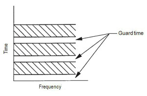
Figure 5 TDMA.
TDMA is a time-sharing scheme in which stations are allocated specific time slots in which to operate. Figure 5 shows the relationship of time and frequency for TDMA operation. It can be seen that there are specific times for each system, with guard times between so there is no interaction between stations. In a TDMA scheme, each channel is assigned specific times to transmit and to receive. During the times not allotted to them, they cannot perform their assigned functions. This may seem problematic, but these are short times, on the order of millisecond and microseconds, where interruptions in transmission or reception are not noticed.
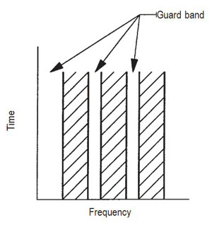
Figure 6 FDMA.
FDMA is illustrated in Figure 6. Each station is on all the time but is assigned certain frequencies in which to operate. There also are spaces between stations in this scheme, called guard bands, which serve the same purpose as the guard times in TDMA. FDMA is the method with which most people are familiar (although they may not realize it), because it is used in AM and FM radio and television. Each station, or channel, is assigned a specific frequency on which to transmit. The stations are on all the time at their assigned frequencies. There also are bands between stations so that an easy listening radio station does not interfere with a rock station or a television sitcom does not interfere with the evening news.