
This article introduces wideband millimeter wave propagation measurements and the sliding correlator channel sounder system used to measure millimeter wave channels in New York City. The measurement system includes a 400 to 750 Megachips-per-second sliding correlator channel sounder that utilizes steerable directional horn antennas at both the transmitter and receiver. Several recent propagation measurement campaigns were conducted by the NYU WIRELESS research center in indoor and outdoor environments at the 28 and 73 GHz millimeter wave bands, resulting in directional and omnidirectional path loss models and multipath spread characteristics that are presented here. Measurement results for directional path loss, omnidirectional path loss and RMS delay spread are presented here. These results will help engineers design future millimeter wave wireless communications systems and will assist in the standardization of millimeter wave wireless networks.
As the wireless industry prepares for the impending fifth-generation (5G) wireless technology to meet the projected 1,000 × growth in user demand in the coming decade, there is a need for accurate and comprehensive channel models at millimeter wave frequencies.1,2,4,5 Unlike previous generations of cellular technology, 5G will likely make use of the millimeter wave spectrum while also using existing UHF/microwave frequencies.
Millimeter wave frequencies (30 to 300 GHz) show great promise for the future of wireless communications because of the large raw available, unused bandwidth. In particular, over 14 GHz of available spectrum exists in the 28, 38/39, and 73 GHz bands, making these bands excellent candidates for new mobile spectrum that will increase capacity by several orders of magnitude over today’s cellular and Wi-Fi allocations.2,5 Recent advances in integrated circuit and antenna technology have made it possible to inexpensively and reliably manufacture wireless devices that operate at millimeter wave frequencies.1,4,15,32
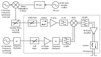
Figure 1 Block diagram of the transmitter used to characterize the 73 GHz channel.
Millimeter wave frequencies have not been widely used for personal communications to date because of a lack of available electronic components and a common belief that rain and atmospheric attenuation are too high for mobile access communications at these high frequencies. However, in reality the additional attenuation at millimeter wave frequencies will be negligible for coverage distances on the order of several hundred meters.5-7 Urban cellular deployments already use smaller cell sizes to meet growing capacity demands, thus millimeter wave cells will have similar density to deployments in use in today’s urban areas.6
The uncharted millimeter wave spectrum requires carefully planned measurements in order to develop channel models to support equipment design and the standardization process of the air interface. Since 2012, the NYU WIRELESS research center has performed measurements at 28 and 73 GHz in New York City. These measurements have been used to develop channel models that are being used by researchers throughout industry and academia.4-14,27,28 Earlier measurements in Austin, Texas during the summer of 2011 explored the 38 and 60 GHz bands, using a 400 and 750 Megachips-per-second (Mcps) spread spectrum binary phase shift keying (BPSK) channel sounder, very similar to the channel sounder used for the New York City measurements.20,26,29,30,31
Measurement Approach and Test System

Figure 2 Block diagram of the receiver used to characterize the 73 GHz channel.
To conduct wideband millimeter wave channel measurements with angle of arrival and departure information, as well as high resolution multipath and received power, NYU WIRELESS makes use of a custom-built BPSK sliding correlator channel sounder. Unlike systems using vector network analyzers, there is no need for phasing cables between the transmitter (Tx) and receiver (Rx). Without the need for connecting the Tx and Rx, separation distances can be measured up to hundreds of meters in non-line-of-sight (NLOS) conditions. The system triggers from the strongest arriving multipath energy and is being upgraded with GPS-controlled cesium-standard clocks for absolute timing measurements.
The use of sliding correlation allows the channel sounder to measure over very large bandwidths.3,25 Transmission begins with the generation of a baseband pseudorandom noise (PN) signal. The PN sequence is created by an 11-bit linear feedback shift register (LFSR), yielding a PN sequence with a length of 211-1 = 2047.
At the receiver, the signal is demodulated into its baseband in-phase (I) and quadrature (Q) components. These signals are then cross-correlated with a PN sequence identical to the Tx. The PN sequence at the Rx, however, is generated at a chip rate slightly offset from the Tx chip rate. For the outdoor New York City measurements, the Tx transmits at 400 Mcps and the Rx chip rate is 399.95 Mcps. The offset in chip rates gives rise to the slide factor, Υ, which is calculated as:

where fc and fc' are the Tx and Rx chip rates, respectively.3,16
Due to the autocorrelation properties of PN sequences, the cross-correlation will be orders of magnitude larger when the two sequences are aligned than when not. These correlations can be performed separately but concurrently for the I and Q components, yielding two signals I(τ) and Q(τ).17 The correlation peaks that occur when the sequences are aligned can be sampled and used to recover the channel’s power delay profile (PDP) p(τ).

One of the most important features of the sliding correlator is the time dilation it provides. The sliding correlator has the effect of compressing the PDP’s bandwidth drastically, equivalent to the original Tx chip rate divided by the slide factor.3,18 For chip rates of 400 Mcps at the Tx and 399.95 Mcps at the Rx, the signals I(τ) and Q(τ) will each have a bandwidth of only 50 kHz.
Although the sliding correlation process approximates the autocorrelation of a PN sequence, there is still improvement to be made after the time-dilated PDP has been recovered. The compression to a very narrow bandwidth offers the opportunity to lowpass filter the signal and reject a considerable amount of distortion that is present at higher frequencies.16 Once this signal has been filtered, the true un-dilated PDP can be recovered.
There are several parameters that influence the performance of a sliding correlator, but the dynamic range in particular is often the greatest concern when considering channel sounder performance.19 The theoretical dynamic range is determined from the length of the PN sequence, and is 66.2 dB for a sequence of length 2047.19
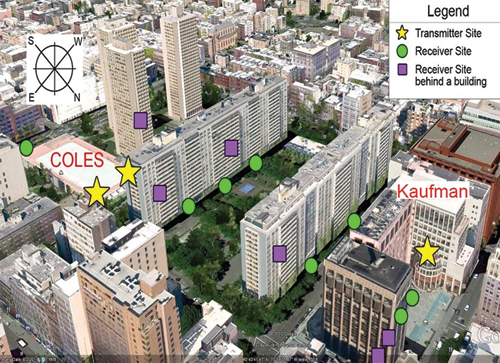
Figure 3 28 GHz measurement sites near NYU's Manhattan campus.
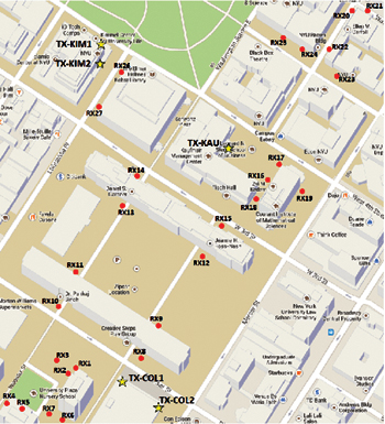
Figure 4 73 GHz measurement sites around NYU's Manhattan campus.
Figure 1 shows the block diagram of the transmitter system for the 73 GHz measurements. The channel sounding system uses QuickSyn signal generators provided by National Instruments (NI) for an intermediate frequency (IF) at 6.625 GHz. The 400 Mcps baseband PN sequence, produced by a PN sequence generator, is first mixed with the 5.625 GHz IF to obtain the second stage IF spread spectrum signal. The 22.625 GHz LO frequency is tripled by a frequency multiplier to 67.875 GHz, which drives the mixing operation with the spread spectrum IF signal. This generates a spread spectrum RF signal centered at 73.5 GHz with an 800 MHz first null-to-null RF bandwidth.10
Figure 2 shows the block diagram of the receiver system for 73 GHz measurements. The received signal is down-converted from the 73.5 GHz RF to the 5.625 GHz IF. The LO frequency at 22.625 GHz is the same as on the Tx side. The sliding process correlates the 399.95 Mcps baseband signal generated by the Rx PN sequence generator and the baseband equivalent received I and Q signals from the down-converter, resulting in a time-dilated autocorrelation with a bandwidth of 50 kHz. The NI DAQ digitizer samples the time-dilated pulse on both the I and Q channels at 2 Mega-samples-per-second (Msps). The Tx and Rx channel sounder block diagrams for 28 GHz are very similar to those shown for 73 GHz in Figures 1 and 2.
Directional horn antennas with various directive gains are used to provide spatial discrimination similar to what will be used in future millimeter wave systems.1,15,32 By using directional antennas that can be rotated in the azimuth and elevation planes, angle of arrival (AOA) and angle of departure (AOD) information can be obtained by taking measurements across different AOA and AOD combinations.
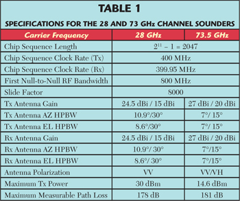
Table 1 summarizes the specific parameters of the channel sounders used for each measurement campaign. AZ denotes azimuth, EL is elevation and HPBW is half-power beamwidth. VV indicates that the Tx and Rx horn antennas are both vertically polarized; VH denotes that the Tx antenna is vertically polarized and that the Rx antenna is horizontally polarized.
Outdoor Measurement Campaigns
The 28 GHz outdoor propagation measurements were conducted at three transmit locations and 25 receive locations in downtown Manhattan,8 shown in Figure 3. The three transmit locations are depicted with yellow stars, and the receive locations with green circles and purple squares. The green circles represent visible receive sites, and the purple squares depict receive locations blocked by obstructions in this view.
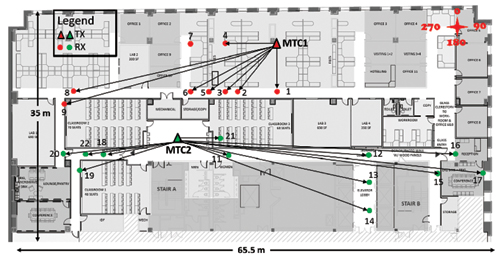
Figure 5 Locations for the 73 GHz indoor measurements.22

Figure 6 28 GHz and 73 GHz close-in free space reference distance directional path loss in the outdoor urban environment of New York City, and indoor path loss models. 28 GHz outdoor directional path loss models (a). 73 GHz outdoor directional path loss models, considering access and backhaul Rx heights (b). 73 GHz indoor directional path loss models with VV and VH antenna polarization (c).
The 75 total Tx-Rx combinations comprised of Tx-Rx separation distances from 19 to 425 m. The channel sounder employed a 24.5 dBi gain antenna (10° HPBW) at the Tx, and either a 15 dBi (30° HPBW) or 24.5 dBi gain antenna (10° HPBW) at the Rx. The measurements were performed for a base station-to-mobile scenario, with Rx antennas at a mobile height of 1.5 m. Tx antennas were placed on relatively low rooftops, with two Tx locations 7 m above ground level (AGL) and one Tx location 17 m AGL. For each Tx-Rx location combination, 10 sets of measurements were conducted for various Tx and Rx azimuth and elevation angle configurations.
In addition to the Manhattan measurements, 28 GHz outdoor propagation measurements were also performed in downtown Brooklyn. These measurements were conducted for one Tx and 11 Rx locations, with the Tx-Rx separation distance ranging from 75 to 125 m. At three locations, the Rx was moved in half-wavelength increments on an automated 10-wavelength long linear track. This configuration studied small-scale fading, which impacts MIMO performance.23
The 73 GHz outdoor propagation measurements were conducted in downtown Manhattan, at five transmit and 27 receive locations, as shown in Figure 4. The five transmit locations are denoted by yellow stars. Two were on the two-story rooftop of the Coles Recreational Center (7 m high), two on the second floor balcony of the Kimmel Center (7 m high), and one on the fifth-story balcony of the Kaufman building of the Stern Business School (17 m high). Tx-Rx separation distances ranged from 30 to 216 m.
A total of 36 unique mobile access and 38 backhaul link combinations were measured. Rx antennas at heights of 2 and 4.06 m were used to emulate base station-to-mobile links and wireless backhaul links, respectively. For each Tx-Rx combination, up to 12 measurement sweeps were conducted to generate omnidirectional path loss models.12
Indoor Measurement Campaign
An extensive indoor propagation measurement campaign at 73 GHz was conducted for different antenna polarizations to model a typical office environment. To measure the co- and cross-polarized channel characteristics, a pair of 20 dBi (15° HPBW) antennas was used. Two transmit and 21 receive locations, shown in Figure 5, were chosen to investigate the complex indoor propagation channels.
The Tx-Rx separation distance ranged from 6 to 46 m. The Tx antenna was set at a height of 2.5 m near the ceiling to imitate current indoor wireless access points; the Rx was set at a height of 1.5 m (similar to the height of a mobile phone carried by a person). For each Tx and Rx location combination, eight measurements with various AOD and AOA and co- and cross-polarization combinations were measured.21
Measurement Results
Measurement results from the 28 and 73 GHz outdoor and 73 GHz indoor campaigns include directional path loss models, omnidirectional path loss models and direction root mean square (RMS) delay spread characteristics.
Directional path loss values were obtained from individual unique pointing angles for all measurements. Directional path loss models are important, since 5G systems will use narrow beam directional antennas and will take advantage of beamforming and beam combining technologies.
Close-in free space reference distance path loss at a reference distance d0 is expressed by the following equation:

where N is the best fit minimum mean square error (MMSE) path loss exponent (PLE), and Xσ is a zero mean Gaussian random variable with a standard deviation σ in dB, also known as the shadowing factor, caused by large-scale random variations in the channel.3 The PLE is introduced to describe the propagation attenuation caused by the channel.
Figure 6 shows outdoor directional path loss models using a 1 m close-in free space reference distance for 28 and 73 GHz. Red crosses represent the NLOS path loss value measurements, blue triangles represent the best path loss values for a specific Tx-Rx location combination and green circles represent line-of-sight (LOS) path loss. Path loss models are simplified using a d0 of 1 m, as it removes the denominator term seen in Equation 1.

Figure 7 28 GHz and 73 GHz close-in free space reference distance omnidirectional path loss in the outdoor urban environment of New York City, and indoor path loss models. 28 GHz outdoor omnidirectional path loss models (a). 73 GHz outdoor omnidirectional path loss models (b). 73 GHz indoor omnidirectional path loss models with VV and VH antenna polarization (c).
For LOS scenarios, the PLE in outdoor and indoor environments for both 28 and 73 GHz is favorable, close to the theoretical free space path loss (FSPL) of n = 2.
The NLOS measurements also include measurements at LOS environment when the TX and RX antennas are not directly on boresight with each other. For NLOS scenarios, Figure 6a shows a PLE of 4.5 for all locations in 28 GHz outdoor measurements with 24.5 dBi narrow beam co-polarized antennas. Figure 6b shows a PLE of 4.7 for 73 GHz outdoor measurements, and Figure 6c shows a PLE of 5.1 for 73 GHz indoor measurements with co-polarized antennas.
NLOS-best denotes the lowest path loss observed at a unique pointing angle for the directional NLOS channel for each Tx-Rx location combination. Figure 6 shows that the NLOS-best PLE is 3.7 for 28 GHz outdoor and that the NLOS-best PLE is 3.6 and 3.3 for 73 GHz outdoor and indoor measurements, respectively. This improvement in PLE when considering the best NLOS angles is significant and shows the advantage of using beam searching and directional antennas at millimeter wave frequencies. The NLOS path loss experienced large attenuation per decade; however, the use of multiple antenna elements and beamforming and beam combining technologies can significantly decrease the path loss when considering the best possible paths.
The results show that beam combining can significantly reduce the propagation PLE32. PLE for certain Tx and Rx combinations reduces from 4.7 to 3.6 for 73 GHz outdoor scenarios using a 1 m free space reference distance. By coherently combining the four strongest signals from four distinct beams, compared to an arbitrarily pointed single beam, 28 dB of link improvement is achieved, and 10 dB of improvement when compared to a single optimum beam over a 100 m Tx-Rx separation at 73 GHz. For the 28 GHz outdoor measurements, the maximum possible improvement reaches 24 dB. The cross polarization measurements also show the potential for antenna polarization diversity systems in indoor millimeter wave communications systems.21
Omnidirectional Path Loss
Omnidirectional path loss models are important, since they allow an arbitrary antenna pattern to be used in simulation or analysis. The existing 3GPP WINNER II and other 3GPP-like models are omnidirectional for this reason. To create omnidirectional models for each Tx-Rx location combination, the received powers at every unique azimuth and elevation angle combination were summed after removing antenna gains. This yields an omnidirectional received power for each Tx-Rx location combination, used to compute an omnidirectional path loss model.6,14,21
Figure 7a shows the omnidirectional path loss models for 28 GHz outdoor LOS and NLOS measurements using a 1 m close-in reference distance. The LOS PLE of 2.3 is very close to the theoretical FSPL and has a small shadowing factor of 2.6 dB. The NLOS PLE is 3.4 with a standard deviation of 9.7 dB.14 Figure 7b shows the omnidirectional path loss models for 73 GHz outdoor LOS and NLOS measurements, combining the access and backhaul scenarios. The LOS PLE and NLOS PLE are similar to the 28 GHz outdoor measurements. Figure 7c shows the omnidirectional path model for the 73 GHz indoor measurements. The LOS PLE for VV polarization is 1.5 with shadowing factor of 0.8 dB. The corresponding LOS PLE and shadowing factor for the cross-polarized antenna are 4.5 and 6.6 dB, respectively. The NLOS omnidirectional PLE and shadowing factor for co- and cross-polarized antenna are 3.1 and 8.9 dB; and 5.3 and 0.69 dB, respectively.
The indoor omnidirectional co-polarized path loss results are very promising for an indoor environment, as the LOS PLE is lower than true free space, due to ground bounces and constructive interference from reflections. The NLOS PLE of 3.1 is also reasonable for an indoor wireless network.21
RMS Delay Spread
RMS delay spread is one of the most important characteristics of a radio propagation channel, as it describes the multipath time dispersion of the channel used to estimate data rate and bandwidth limitations for multipath channels.3,4 To build power-efficient millimeter wave mobile communication systems with simple equalization, the ideal situation is for particular beam pointing directions to offer both minimal path loss and minimal multipath delay spread. If the channel provides such paths, simplified receiver structures can be based solely on beamforming and minimal equalization in the time domain, rather than using multi-tone, OFDM modulation and frequency domain equalization, as is done today.4
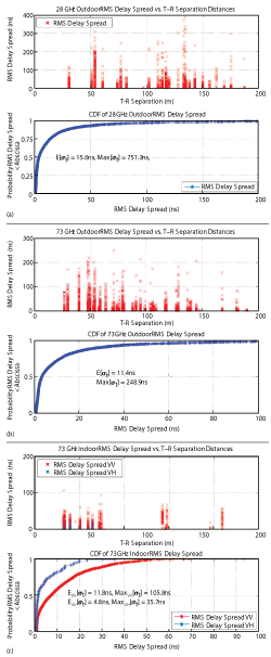
Figure 8 28 and 73 GHz RMS delay spread CDFs and RMS delay spread as function of Tx-Rx separation distance. 28 GHz outdoor measurements (a). 73 GHz outdoor measurements (b). 73 GHz indoor measurements (c).
For this unique pointing angle scenario, Figure 8 shows the RMS delay spread as a function of Tx-Rx separation and the associated cumulative distribution functions (CDFs) for 28 and 73 GHz outdoor and 73 GHz indoor measurements. The RMS delay spread in the 28 GHz outdoor measurements with 24.5 dBi gain narrow beam antennas shows that the majority of the multipath components arrive within about 50 ns. The RMS delay spread in the 73 GHz outdoor measurements with 27 dBi gain narrow beam antennas, combining backhaul and access scenarios, shows that a majority of the multipath components arrive within about 30 ns. For the 73 GHz indoor measurements, the majority of the multipath for co-polarized antennas arrives within about 35 ns, and for cross-polarized antennas within about 20 ns.
Generally, the RMS delay spread decreases as the Tx-Rx separation distance increases, since weaker components reaching the receiver at greater distances are not detectable above the receiver system’s noise floor.24
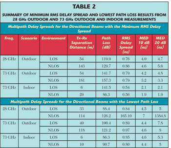
Table 2 summarizes Tx-Rx separation distance, path loss, RMS delay spread, maximum 10 dB down excess delay3 and maximum 20 dB down excess delay for specific antenna pointing angles. The characteristics are presented for two case-types in the table: values for one particular Tx-Rx angle pointing orientation that provides the minimum RMS Delay Spread for that case and values for one particular Tx-Rx angle pointing orientation that results in the minimum path loss, for the same Tx-Rx location combination. The values are determined from the entire measurement set that provided the smallest directional RMS delay spread and path loss.21-23
A simple algorithm to find the best beam directions will help simultaneously minimize both RMS delay spread and path loss (i.e., finding the best paths for both maximum SNR and very simple equalization).23 By selecting a beam with both low RMS delay spread and path loss, relatively high power can be received using directional antennas without complicated equalization, meaning that low latency single carrier (wideband) modulations may be viable candidates for future millimeter wave wireless systems. The measured values presented here are useful to the research community for understanding values that may result when beamforming or beam searching algorithms are used to systemically search for the strongest Tx and Rx pointing angles, to achieve the lowest path loss or link attenuation.
Conclusion
This article describes the sliding correlator channel sounder system and presents the millimeter wave propagation measurements performed by NYU WIRELESS over the past two years. Results are shown for 28 GHz outdoor, 73 GHz outdoor base station-to-mobile (access), 73 GHz base station-to-base station (backhaul) and 73 GHz indoor scenarios. The measurement results include channel characteristics such as directional and omnidirectional path loss models relative to a 1 m free space reference distance, and directional delay spread.
The path loss model results obtained for unique pointing angles show that LOS free space propagation in outdoor (n = 2.3) and indoor environments (n = 2.2) for the 73 GHz band and outdoor environments (n = 1.9) for the 28 GHz band is favorable and close to the theoretical free space path loss (n = 2). The NLOS environment at 28 and 73 GHz experiences greater attenuation than the LOS environment yielding n = 4.1 for the 28 GHz outdoor directional measurements n = 4.7 for the 73 GHz outdoor scenario, and n = 5.1 for 73 GHz indoor measurements. However, with the use of multiple antenna elements, beamforming and beam combining technologies can significantly decrease the path loss when considering the best possible paths (n = 3.7 for 28 GHz outdoor, n = 3.6 for 73 GHz outdoor, and n = 3.3 for 73 GHz indoor co-polarization). The omnidirectional co-polarized path loss results are very promising for an indoor environment, as the LOS path loss exponent is smaller than for true free space, due to ground bounces and constructive interference from reflections.
RMS delay spread is generally inversely proportional to the Tx-Rx separation distance. Understanding RMS delay spread in the millimeter wave bands is important for wireless communications systems, especially where beam combining, beamforming and equalization are necessary to increase the signal-to-noise ratio (SNR) and improve performance for a communication system.
The data described in this article will allow for the development of statistical channel models for millimeter wave small cell wireless communications systems in dense urban environments. Statistical models in the form of 3GPP standards have already been published based on the measurements described.14,27,28 Given the large availability of spectrum at 28 and 73 GHz, millimeter wave bands will likely play a significant role in the next generation of cellular systems and these measurements and models will be an essential tool in their design.
References
- T.S. Rappaport, J.N. Murdock and F. Gutierrez, ‘‘State of the Art in 60-GHz Integrated Circuits and Systems for Wireless Communications,’’ Proceedings of the IEEE, August 2011, pp. 1390-1436.
- A. Ghosh, T.A Thomas, M.C. Cudak, R. Ratasuk, P. Moorut, F.W. Vook, T.S. Rappaport, G.R. MacCartney, S. Sun and S. Nie “Millimeter-Wave Enhanced Local Area Systems: A High-Data-Rate Approach for Future Wireless Networks,” Selected Areas in Communications, IEEE Journal, pp. 1152-1163, June 2014.
- T.S. Rappaport, Wireless Communications: Principles and Practice, 2nd ed. Upper Saddle River, NJ: Prentice Hall, 2002.
- T.S. Rappaport, R.W. Heath Jr., R.C. Daniels and J.N. Murdock, Millimeter Wave Wireless Communications, Pearson/Prentice Hall, c. 2015.
- T.S. Rappaport, S. Sun, R. Mayzus, H. Zhao, Y. Azar, K. Wang, G.N. Wong, J.K. Schulz, M.K. Samimi and F. Gutierrez, “Millimeter Wave Mobile Communications for 5G Cellular: It Will Work!” IEEE Access, pp. 335-349, 2013.
- S. Rangan, T.S. Rappaport and E. Erkip, “Millimeter-Wave Cellular Wireless Networks: Potentials and Challenges,” Proceedings of the IEEE, pp. 366-385, March 2014.
- G.R. MacCartney, Jr., J. Zhang, S. Nie and T.S. Rappaport, “Path Loss Models for 5G Millimeter Wave Propagation Channels in Urban Microcells,” 2013 IEEE Global Communications Conference (GLOBECOM), December 2013, pp. 3948-3953.
- Y. Azar, G.N. Wong, K. Wang, R. Mayzus, J.K. Schulz, H. Zhao, F. Gutierrez, Jr., D. Hwang and T.S. Rappaport, “28 GHz Propagation Measurements for Outdoor Cellular Communications Using Steerable Beam Antennas in New York City,” 2013 IEEE International Conference on Communications (ICC), June 2013, pp. 5143-5147.
- M.K. Samimi, K. Wang, Y. Azar, G.N. Wong, R. Mayzus, H. Zhao, J.K. Schulz, S. Sun, F. Gutierrez, Jr. and T.S. Rappaport, “28 GHz Angle of Arrival and Angle of Departure Analysis for Outdoor Cellular Communications Using Steerable Beam Antennas in New York City,” 2013 IEEE 77th Vehicular Technology Conference (VTC Spring), June 2013, pp. 1-6.
- S. Nie, G. R. MacCartney, S. Sun and T. S. Rappaport, “73 GHz Millimeter Wave Indoor Measurements for Wireless and Backhaul Communications,” 2013 IEEE 24thInternational Symposium on Personal Indoor and Mobile Radio Communications (PIMRC),September 8-11, 2013, pp. 2429–2433.
- S. Sun, G.R. MacCartney Jr., M.K. Samimi, S. Nie and T.S. Rappaport,“Millimeter Wave Multi-Beam Antenna Combining for 5G Cellular Link Improvement in New York City,” 2014 IEEE International Conference on Communications (ICC), June 2014.
- G.R. MacCartney Jr. and T.S. Rappaport,“73 GHz Millimeter Wave Propagation Measurements for Outdoor Urban Mobile and Backhaul Communications in New York City,” 2014 IEEE International Conference on Communications (ICC), 2014 IEEE, June 2014.
- S. Nie, G.R. MacCartney, S. Sun and T.S. Rappaport, “28 GHz and 73 GHz Signal Outage Study for Millimeter Wave Cellular and Backhaul Communications,” 2014 IEEE International Conference on Communications (ICC), June 2014.
- G.R. MacCartney, M.K. Samimi and T.S. Rappaport, “Omnidirectional Path Loss Models in New York City at 28 GHz and 73 GHz,“ IEEE 2014 Personal Indoor and Mobile Radio Communications (PIMRC), September 2014, Washington, DC.
- F. Gutierrez, S. Agarwal, K. Parrish and T.S. Rappaport, On-Chip Integrated Antenna Structures in CMOS for 60 GHz WPAN Systems, IEEE Journal on Selected Areas in Communications, Vol. 27, Issue 8, October 2009, pp. 1367-1378.
- R.J. Pirkl and G.D. Durgin, “Optimal Sliding Correlator Channel Sounder Design,” IEEE Transactions on Wireless Communications, September 2008, pp. 3488-3497.
- D.C. Cox. “910 MHz Urban Mobile Radio Propagation: Multipath Characteristics in New York City,” IEEE Transactions on Vehicular Technology, November 1973, pp. 104-110.
- R.J. Pirkl and G.D. Durgin, “How to Build an Optimal Broadband Channel Sounder,” 2007 IEEE Antennas and Propagation Society International Symposium, June 2007, pp. 601-604.
- G. Martin. “Wideband Channel Sounding Dynamic Range using a Sliding Correlator,” IEEE 2000 Vehicular Technology Conference Proceedings, 2000, pp. 2517-2521.
- E. Ben-Dor, T.S. Rappaport, Y. Qiao and S.J. Lauffenburger, “Millimeter-Wave 60 GHz Outdoor and Vehicle AOA Propagation Measurements Using a Broadband Channel Sounder,” 2011 IEEE Global Telecommunications Conference (GLOBECOM 2011), December 5-9, 2011, p. 1-6.
- S. Nie, M. K. Samimi, T. Wu, S. Deng, and T. S. Rappaport, “73 GHz Millimeter-Wave Indoor and Foliage Propagation Channel Measurements and Results,” NYU WIRELESS: Department of Electrical and Computer Engineering, NYU Polytechnic School of Engineering, Brooklyn, New York, Tech. Rep. 2014-003, July 2004.
- T.S. Rappaport, G.R. MacCartney Jr., M.K. Samimi and S. Sun, “Wideband Millimeter-Wave Propagation Measurements and Channel Models for Future Wireless Communication System Design” invited, IEEE Transactions on Commumications, to be published.
- S. Sun, T.S. Rappaport, R.W. Heath, A. Nix and S. Rangan, “MIMO for Millimeter Wave Wireless Communications: Beamforming, Spatial Multiplexing, or Both?” IEEE Communications Magazine, Vol. 52, No. 12, December 2014.
- T.S. Rappaport and D.A. Hawbaker, “Wideband Microwave Propagation Parameters using Circular and Linear Polarized Antennas for Indoor Wireless Channels,” IEEE Transactions on Communications, February 1992, pp. 240-245.
- W.G. Newhall, T.S. Rappaport and D.G. Sweeney, “A Spread Spectrum Sliding Correlator System for Propagation Measurements,” RF Design, April 1996, pp. 40-54.
- T.S. Rappaport, E. Ben-Dor, J.N. Murdock and Y. Qiao, “38 GHz and 60 GHz Angle-Dependent Propagation for Cellular and Peer-to-Peer Wireless Communications,” 2012 IEEE International Conference on Communications (ICC), June 2012, pp. 4568-4573.
- T.A. Thomas, H.C. Nguyen, G.R. MacCartney Jr. and T.S. Rappaport, “3D mmWave Channel Model Proposal,” 2014 IEEE Vehicular Technology Conference (VTC Fall), 80th, September 14-17, 2014.
- M.K. Samimi, T.S. Rappaport, “Ultra-Wideband Statistical Channel Model for Non Line of Sight Millimeter-Wave Urban Channels,” IEEE Global Communications Conference, Exhibitions & Industry Forum (GLOBECOM), December 8-12, 2014.
- T.S. Rappaport, E. Ben-Dor, J.N. Murdock, Y. Qiao and J. Tamir, “Cellular and Peer-to-Peer Broadband Millimeter Wave Outdoor Propagation Measurements and Angle of Arrival Characteristics using Adaptive Beam Steering,” IEEE Radio and Wireless Symposium (RWS) 2012, Santa Clara, CA, January 15, 2012.
- J.N. Murdock, E. Ben-Dor, Y. Qiao, J.I. Tamir and T.S. Rappaport, “A 38 GHz Cellular Outage Study for an Urban Outdoor Campus Environment,” IEEE Wireless Communications and Networking Conference (WCNC), April 2012.
- A.I. Sulyman, A.T. Nassar, M.K. Samimi, G.R. MacCartney Jr., T.S. Rappaport and A. Alsanie, “Radio Propagation Path Loss Models for 5G Cellular Networks in the 28 GHz and 38 GHz Millimeter-Wave Bands,” IEEE Communications Magazine, September 2014, Vol. 52, No. 9, pp. 78-86.
- W. Hong, K.H. Baek, Y. Lee and Y. Kim, “Study and Prototyping of Practically Large-Scale mmWave Antenna Systems for 5G Cellular Devices,” IEEE Communications Magazine, Vol. 52, No. 9, September 2014.