
LTE has become a global phenomenon: By August 2013, a total of 204 LTE networks in 77 countries were commercially operated. With only four years of real-life deployment, however, the technology is still in its infancy compared with 2G/3G technologies. But time in mobile communications moves quickly, and significant improvements were added to the initial LTE technology as specified in 3GPP Release 8.
In LTE 3GPP Release 9, the main improvements are support for multimedia broadcast multicast services (eMBMS), positioning and, last but certainly not least, optimizations such as semi-persistent scheduling (SPS) and transmission time interval (TTI) bundling in order to more efficiently support voice services. 3GPP Release 10 – the start of LTE-Advanced – added technology components that are even more significant. The one that is most in demand is carrier aggregation, which is already in commercial use and allows more efficient utilization of the fragmented spectrum available to an individual operator.
The next set of improvements was added in 3GPP Release 11. For this release, the core network and radio access protocols were finalized in December 2012 and June 2013, respectively. Defining test specifications, of course, takes additional time. This article introduces coordinated multipoint operation (CoMP), an enhancement that was initially discussed in the 3GPP Release 10 time frame. CoMP is widely talked about and applicable to the cellular industry. This article also examines the impact on testing both base station and end-user devices that support CoMP.
CoMP and LTE-Advanced
CoMP for LTE is one of the most important technical improvements with respect to heterogeneous network (HetNet) deployment strategies, but also for the traditional homogeneous network topology. In brief, HetNets aim to improve spectral efficiency per unit area using a mixture of macrocell, picocell and femtocell base stations and/or remote radio heads (RRH).
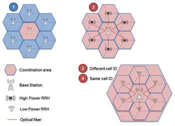
Figure 1 Coordinated multipoint operation (CoMP) scenarios.
In contrast, homogeneous network topologies comprise cells of about equal size, usually the macro layer. Nevertheless, with both network deployment strategies, cell edge users can experience intercell interference. This type of interference is caused by the downlink transmissions from two (or more) different base stations (cells). In a frequency reuse 1 system like LTE, when the same frequency is used in all cells, this affects in particular user devices at the cell edge. The goal of CoMP is to further minimize intercell interference for cells that are operating on the same frequency. With HetNets, this intercell interference becomes even more significant due to unbalanced output powers used in the macrocell and picocell/femtocell layer.
As the name implies, CoMP will make it possible to coordinate the optimization of transmission and reception from multiple distribution points, which could be either multiple cells or RRHs. CoMP will enable joint transmission and/or reception to mobile devices. It will also have a positive effect on power consumption as well as overall throughput and thus system capacity. Plus, it will allow load balancing between cells that are coordinated.
3GPP standardization is based on four different CoMP scenarios (see Figure 1). The first two scenarios focus on homogeneous network deployments, one with a single eNodeB serving multiple sectors (scenario 1) and the other with multiple high-transmit-power RRHs (scenario 2). The remaining two scenarios target HetNets, where macrocells and small(er) cells are jointly deployed using different cell identities (ID), as shown in scenario 3, or the same cell ID, as shown in scenario 4.
Due to its complexity, CoMP has been separated during the standardization process into two independent work items for downlink and uplink. Both link directions benefit from the two major schemes being used in CoMP: joint processing (JP), which includes joint transmission (JT, downlink) and joint reception (JR, uplink) as well as coordinated scheduling/beamforming.
What’s Important to Know About CoMP?
Performance gains from CoMP result from managing the interference at cell boundaries, specifically in the HetNet scenario. To understand the details behind downlink and uplink CoMP, it is essential to know the terminology used: CoMP cooperating set, CoMP measurement set and CoMP resource management.
CoMP cooperating set: The CoMP cooperating set is determined by higher layers. It is a set of geographically separated distribution points that are directly or indirectly involved in data transmission to a device in a time-frequency resource. Within a cooperating set, there are CoMP points. With regard to the CoMP schemes, the set could contain multiple points at each subframe (e.g., joint transmission) or a single point at each subframe (e.g., coordinated scheduling/beamforming).
CoMP measurement set: The CoMP measurement set is a set of points about which channel state information (CSI) or statistical data related to their link to the mobile device is measured and/or reported. This set is determined by higher layers. A mobile device is enabled to down-select the points for which the actual feedback is reported.
CoMP resource management: The CoMP resource management is a set of CSI reference signal (CSI-RS) resources for which CSI-RS-based reference signal received power (RSRP) measurements can be made and reported.

Figure 2 Downlink CoMP cooperating and measurement set for cells using the same (left) or different (right) cell identity/identities.
Figure 2 shows the CoMP cooperating set and the CoMP measurement set for the two cases defined: Either all cells use different physical cell identities, or multiple cells have the same cell identity. In the latter case, the concept of virtual cell identities (VCID) can be applied. VCIDs are assigned by higher layers.
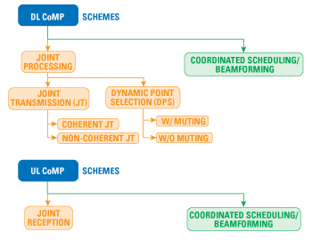
Figure 3 Overview of downlink (DL) and uplink (UL) CoMP schemes.
CoMP Schemes
Figure 3 provides an overview of the CoMP schemes used in the downlink and uplink. In the downlink, joint transmission enables simultaneous data transmission from multiple points to a single UE or even multiple UEs. This implies that the UE data is available at multiple points, belonging to the CoMP cooperating set, throughout the network. The goal is to increase signal quality at the receiver and thus the average throughput. The coherency of JT refers to the ability to form precoders that exploit the phase and possibly amplitude relations between channels associated with different transmission points.
In other words, in coherent JT the signal from multiple transmission points is jointly precoded. In noncoherent JT, the UE would receive multiple signals individually precoded by each transmission point. In general, JT requires a low latency between the transmission points, high-bandwidth backhaul and low mobility UEs. Also for dynamic point selection (DPS), the physical downlink shared channel (PDSCH) data has to be available at multiple points. However, in contrast to JT, data is only transmitted from one point at any given time. For coordinated scheduling/beamforming, the data is only present at one transmission point.
Furthermore, with the coordination of frequency allocations and used precoding schemes (beamforming) at the various transmission points, performance can be increased and interference mitigated. The CoMP schemes implemented for the uplink are similar. For joint reception, the physical uplink shared channel (PUSCH) data transmitted by the UE is received jointly at multiple points (part of or entire CoMP cooperating set) simultaneously to improve the received signal quality.
With regard to coordinated scheduling and beamforming in the uplink, the scheduling and precoding selection decisions are made with coordination among points corresponding to the CoMP cooperating set. But the PUSCH data is intended for one point only. A fundamental change due to CoMP in the LTE uplink is the introduction of virtual cell IDs. As of 3GPP Release 8, the generation of the demodulation reference signal (DMRS) embedded in two defined single carrier frequency division multiple access (SC-FDMA) symbols in an uplink subframe is dependent on the physical cell identity (PCI). The PCI is derived from the downlink.
For future HetNet deployment scenarios, where a macro cell provides the coverage and several small cells are used for capacity, there is higher uplink interference at the cell boundaries. This is especially true for when macrocells and small cells are using the same cell identities. The VCID concept makes it possible to signal a dedicated cell ID via radio resource control (RRC) signaling to be used by the UE for uplink transmission, which allows the UE signal to be received by different reception points.
Testing CoMP
LTE-Advanced CoMP is a complex and powerful technology enhancement. The various downlink and uplink CoMP schemes permitted increase both base station and mobile device complexity. With respect to uplink CoMP, the burden appears on the base station receiver end. More precisely, UE data needs to be transferred between multiple reception points and jointly processed. For intra-eNodeB (intrasector) CoMP, this becomes purely implementation-dependent without impact on testing, since the combining takes place in a single entity.
Simulating multiple UEs for testing the base station receiver is a standard test case used since the beginning of LTE (as well as other cellular technologies). Transferring user data between multiple reception points places latency requirements on the inter-eNodeB interface, which in the best case can be satisfied with fiber connections. Therefore, today’s method for testing a single eNodeB will evolve into testing a distributed base station architecture comprising multiple baseband units (BBU), sometimes also called digital units (DU), in combination with high-power or low-power RRHs (as shown in Figure 1, scenarios 2 to 4).
However, this will not change the testing principle, because the input signal from multiple UEs needs to be provided in the same way as it is today. There also remains the need to verify the signaling information exchange between UE(s) and BBUs combined with RRHs. A new test scenario will likely be added in order to verify the VCID concept. In the downlink, i.e., testing the UE implementation, CoMP requires redesign in the receiver chain because multiple signals from multiple transmission points – potentially on multiple frequencies – need to be successfully combined. In order to allow any CoMP algorithm to schedule the best possible resource from the best possible transmission point, it is essential to have good knowledge of the channel conditions of a particular UE toward the cooperating transmission points.
Consequently, UE measurements on the various reference symbols (cell and channel state information reference symbols [CSI-RS] and interference measurement resources [IMR]) need to be verified. This requires a mobile communications tester to establish multiple scenarios in an easy and efficient way. In contrast to traditional LTE operation, signals from multiple transmission points may expose frequency and time shifts.
Since reporting channel quality information (CQI) is so important, frequency and timing correction measures at the UE end need to be tested extensively as well. The responsible working group (RAN5) in 3GPP has just started drafting the test case details based on initial agreements made in 3GPP RAN4, the group that defines the performance requirements.
Finally, any efficient CoMP algorithm in the network may be applicable to a large number of cells in a certain network area, if not in the complete network. This means that it may be possible to verify whether the implementation-dependent CoMP algorithm is delivering its capacity gain promise by monitoring KPIs in the core network (e.g., overall data throughput per cell). In case of errors, it will be necessary to conduct dedicated drive testing in order to identify the root of a problem.
CoMP is a key technology component in LTE-Advanced 3GPP Release 11 for further increasing system capacity. The advent of continuously increased data consumption specifically on smartphones, along with the anticipated, exponentially growing number of machine-type communications devices such as sensors, makes CoMP the technology of choice for network operators for satisfying capacity needs.
The major design challenge is on the network end, since if coordination is done across multiple cells, high capacity and low latency interfaces between BBUs are required. Additionally, precise knowledge of propagation conditions at the end user position is essential. This requires comprehensive verification of UE reporting behavior under various conditions.