A Direct 64-QAM Modulator Suitable for MMIC Implementation
Surinder Kumar,
Abbas Mohammadi
and David Klymyshyn
Telecommunications Research Labs (TRLabs)
and University of Saskatchewan
Saskatoon, Saskatchewan, Canada
There is considerable worldwide interest in personal communications services (PCS) with wireless data communication. Spectrum allocation for such services has been made and a number of commercial systems are being developed rapidly. It is highly desirable to use the allocated spectrum efficiently. Although the initial systems may use lower level modulation with 1 to 1.5 bps/Hz bandwidth efficiency, future systems will migrate to higher level modulation such as 64-quadrature amplitude modulation (QAM) with up to 4.5 bps/Hz bandwidth efficiency. An important consideration in PCS systems is that the mobile units be compact and power efficient. The conventional method of generating the modulation at the IF followed by upconversion to the transmit frequency is extravagant in power, size and cost. Compared to this method, direct modulation at the transmit frequency leads to a compact circuit that is suitable for MMIC implementation.1,2 When direct modulation is used, the spectrum shaping of the modulated signal must be achieved by baseband prefiltering. It is well known that any nonlinearities in the modulator result in spectrum spreading and signal distortion. An efficient method of overcoming this problem is to use predistortion at baseband. If this method is combined with prefiltering in a digital memory circuit, no additional cost is incurred. Further, the linearization for the modulator and the amplifier can be considered and implemented by the same memory circuit.3 This article presents a direct 64-QAM modulator implementation over the 2.25 to 2.75 GHz frequency band.
Modulator Architecture
The modulator was implemented using microstrip and coplanar lines. The block diagram of the circuit is shown in Figure 1 . The circuit layout is shown in Figure 2 . The first element is a 3 dB Lange coupler, which divides the input signal equally into the in-phase (I) and quadrature (Q) channels. An optimized rat-race power divider is used in both the I and Q channels to divide the signals into 0° and 180° outputs in both paths. A coplanar waveguide structure with PIN diodes is used to implement an SPDT switch for 0¡ and 180¡ signal selection in the I and Q paths. Computer simulation was used to arrive at the coplanar line solution that produced the best isolation over the operating bandwidth (26 dB, compared to 17 dB for microstrip). To realize the eight constellation points in the I and Q paths, a voltage-controlled attenuator is used. Replacing the conventional mixer with this structure eliminates the requirement to use a high Q filter at the mixer output to filter out the LO leakage. Also, the power output of a mixer must be kept low to limit the nonlinear distortion. The use of Lange couplers with PIN diode terminations avoids hystersis effects in the PIN diodes because the diode operation is limited to the forward region only. Avoiding hystersis effects is possible because both in-phase and out-of-phase signals are selected by the SPDT switch preceding the attenuator. The current drivers for the PIN diodes are adjusted to achieve the correct signal levels.
 Fig. 1: The direct QAM modulator's block diagram.
 Fig. 2: The modulator's layout.
One problem that arises with this implementation is that different attenuation levels have different associated phase shifts. This problem was solved by incorporating a phase compensator after the attenuator. Over the 500 MHz operating bandwidth and the attenuation range of -10 to -24 dB, a phase compensation of approximately 30° was required. This compensation level was realized using a reflection phase shifter implemented by terminating a Lange coupler with two varactors at the output paths. The last block in the modulator is a Wilkinson in-phase combiner.
Subsystem and Modulator Computer Simulation
The design was implemented using a 25-mil-thick substrate with Er = 10.8. A series SPDT switch is used to realize unipolar pulse amplitude modulation (PAM). The SPDT is controlled by the polarity of the incoming data. The 0° and 180° outputs of the rat-race coupler were selected based on the positive and negative polarities of the incoming data, respectively. The normalized input and output waveforms for the SPDT with a typical eight-level PAM sequence of 3, -5, 7 are shown in Figure 3 . Although a multisection microstrip SPDT can be realized easily for the desired operating bandwidth, its isolation performance was inadequate. A series SPDT using a coplanar waveguide structure with a gap of 1 mil was examined. This gap improves the isolation of the switch while maintaining a reasonable insertion loss comparable to the microstrip realization. The S-parameters of the switch are shown in Figure 4 for 5 mA forward bias current.
 Fig. 3: The SPDT switch's (a) in-phase and (b) out-of-phase inputs, (c) PAM sequence and (d) normalized output waveform>

Fig. 4: The SPDT's S-parameters at 5 mA forward bias.
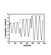
A voltage-controlled attenuator is used to select the different signal levels required for the QAM implementation. The control signals for the attenuator in each path are the absolute values of eight-level PAM. The output of the I path for a typical PAM sequence of 3, -5, 7 is shown in Figure 5 . A reflection attenuator using two PIN diode terminations at the outputs of a Lange coupler is used. This structure offers a dynamic range of 12 dB with a PIN diode current range of 1 to 20 mA over a 500 MHz bandwidth. Figure 6 shows the attenuation level of the RF signal in the I channel for different values of the PIN diode bias current. The attenuation is flat over the operating bandwidth. The PIN diode forward resistance for different bias current values is shown in Figure 7 .
 Fig. 5: The I path's output waveform for the 3, -5, 7 sequence.
 Fig. 6: The I-channel attenuation vs. PIN diode current.
 Fig. 7: PIN diode forward resistance vs. bias current.
A reflection phase shifter compensates for the phase change with attenuation in the voltage-controlled attenuator. This phase shift for different levels of attenuation is approximately 30°. The phase compensation must be performed without introducing any corresponding level change. As shown in Figure 8 , the phase compensation at 5 mA PIN diode bias is achieved with little change in the signal level.
 Fig. 8: Phase shifter attenuation vs. varactor bias.
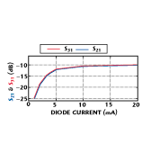
The modulator constellation diagram over the 500 MHz operating bandwidth is shown in Figure 9 . The QAM signal vector errors over the 20 percent bandwidth are less than 10 percent. The insertion loss in the I and Q paths for different values of the PIN diode current is shown in Figure 10 . Figure 11 shows the return loss of the modulator and the phase difference in the I and Q paths for different bias currents. The nonlinear behavior of the modulator can be linearized using predistortion in the bias current driving circuit. This predistortion can be combined with prefiltering and implemented using digital memory circuits.3,4 This procedure facilitates the required spectrum shaping of the modulated signal.
 Fig. 9: The modulator's overall constellation diagram.
 Fig. 10: I and Q path insertion loss vs. PIN diode current.
 Fig. 11: The modulator's (a) return loss and (b) I and Q path phase difference vs. PIN diode current.
Conclusion
A direct 64-QAM modulator implementation has been presented. Greater than 25 percent operating bandwidth was realized while maintaining the vector errors at less than 10 percent. Linearization was implemented through predistortion of the attenuator drive waveforms. Phase compensation was used to keep the phase errors small. Eight PIN diodes and four varactors were used to implement the modulator, resulting in a cost-effective design that is suitable for MMIC implementation. Combined with the high bandwidth efficiency of 64-QAM modulation, such a modulator is highly attractive for emerging high volume PCS-type applications.
Acknowledgment
The simulation results were generated using EEsof software. The PIN diodes and varactor used were the models 1304 and 120412, respectively, from Alpha Industries, Woburn, MA. The manufacturer provided S-parameters that were used for these devices in the simulator.
References
- I. Telliez, A. Couturier, C. Rumelhard, C. Versnaeyen, P. Champion and D. Fayol, "A Compact Monolithic Microwave Demodulator for 64-QAM Digital Radio Links," IEEE Transactions on MTT , Vol. 39, No. 12, December 1991, pp. 1947-1953.
- L.M. Devlin and B.J. Minnis, "A Versatile Vector Modulator Design for MMIC," IEEE MTT-S Digest , 1990, pp. 519-522.
- K. Kathiravan, S. Kumar and G. Harron, "Combining Prefiltering and Predistortion in a High Power Direct PSK Modulator," IEEE MTT-S Digest , 1990, pp. 877-880.
- S. Kumar, "Power Amplifier Linearization Using MMICs," Microwave Journal , April 1992, pp. 96-104.
