
Modern microwave communication systems have to comply with hard requirements for small size, low cost and reduced power consumption. In order to obtain a final system with such specifications, a commonly used approach is the combination of some functionalities of the system on a single circuit, reducing the number of components and the final cost of the system.1
Doppler radars are widely used for various purposes, including near distance motion detections. Examples include vehicle equipment, measurement of water surface velocity, detection of acoustic vibrations, non-contact cardiopulmonary monitoring and proximity motion detection in which the system's microwave front-end consists of several components. Some examples are one or two antennas, a local oscillator, one or two hybrids and/or an isolator, a frequency mixer and bandpass filters.
In order to reduce the number of components, hence to save on the size and cost of the Doppler radar, a self-oscillating mixer (SOM) could be adopted.2 There are various advantages related to the self-oscillating mixer technique: cost is reduced, due to a lowered component count and thus higher reliability, the more compact solution offers easier integration into monolithic microwave integrated circuits (MMIC) and the total power consumption is lowered.3
The performance limits in Doppler radar sensing depend mainly on mixer conversion loss at baseband, and phase noise of the local oscillator signal in the RF band.4 Hence, in this work, a Doppler radar is designed, based on SOM, for short-distance motion detections, with simplicity, low cost and low emitting power. For further reducing the cost and complexity with the least degradation of performance related to the SOM's phase noise, dielectric resonator is replaced with a new slotted-square-patch resonator (SSPR), which is easy to fabricate. For maximizing the conversion gain of the SOM, an optimization technique based on constant gain curves is carried out. The high conversion gain is helpful in reducing the emitted power from the Doppler radar.
Figure 1 Layout of the designed SSPR.
Microstrip SSPR
Phase noise is one of the most important performance parameters of an oscillator. For a lower phase noise, a dielectric resonator (DR) is most frequently used in microwave frequencies because of its high quality factor. The DR however has higher cost and additional difficulties in properly positioning it on a post with the exact coupling factor.
Figure 1 is the layout of the SSPR, which is a microstrip patch type resonator with the effective wavelength of nλ/2 and a high Q-factor. The resonator is designed by inserting the successive slot lines of the ratio of r = N/(N1) in the square patch, denoted as (a), (b), (c) and (d) in the figure. Hence, the lengths of (a) to (d) are L×r, L×r2, L×r3 and L×r4, respectively. The slot lines start from the center of one side, L, of the square patch and with the length reduced by the same ratio, r, until it reaches a given slot number or a minimum limited length that can be manufactured. Here, only four successive slots are used.
Figure 2 Resonance frequency and quality factor of the SSPRs, according to the slot ratio :
:
According to the chosen integer N, from 1 to 4 for L = λ/5, four resonators with one λ electrical length were designed. Figure 2 depicts the results of simulations and measurements. The total slot length increases and the line microstrip width decreases with N increasing, hence the resonance frequency decreases and the Q-factor decreases. The measured unloaded Q-factor was 154.1 for N = 1, which is approximately a 13.6 percent improved value, compared to that of the conventional hair-pin resonator.5 The SSPR's improved Q-factor is due to the adoption of a slotted-patch type resonator, which can inherently maximize use of the circuit space and also to use the wider line width of middle part in length of the resonator in which current flow is maximized. The simulations were performed using a commercial 3D electromagnetic simulator, HFSS™. The substrate used is Teflon with a thickness of 0.762 mm, a relative dielectric constant of 3.48 and loss tangent of 0.003.
Figure 3 RF layout of the designed SOM Doppler radar.
SOM Design
The RF-layout for the proposed SOM or SOM Doppler radar circuit is shown in Figure 3. A 50 Ω termination at the left end of the gate transmission line, the self-bias circuit and the IF bandpass filter at the drain transmission line are not shown in the figure. The circuit was simulated using a commercial circuit simulator ADS™ with an HB-simulation test bench. A well-known transistor, NE3508M04, was self-biased near the pinch-off region (VDD = 3 V, VDS = 2 V, IDS = 3 mA, VGS = -0.4 V).
Figure 4 Circuit model for a two-port transistor oscillator.
A transistor oscillator with a one-port negative-resistance is effectively created by terminating a potentially unstable transistor with an impedance designed to drive the device in an unstable region. In the circuit model for a two-port transistor oscillator of Figure 4, the input and output reflection coefficients are generally given by Equations 1 and 2.6 Then the input and output stability circles can be drawn as Figure 5, using the conditions of |Γin| = 1 and |Γout| = 1.6
Figure 5 The input and output stability circles.
The source transmission line L1 in Figure 3 was adjusted for a wider unstable region. The unstable region is inside of the input stability circle and outside of the output stability circle, which is region (b) in Figure 5.
On the other hand, the conversion gain, Gc, for a mixer is generally defined by Equation 3. Here, PRF and PIF are the powers of the received RF signal and the corresponding IF signal, respectively. In order to obtain the maximally optimized Gc, constant conversion gain circles are drawn, which are similar to those of amplifiers, according to ΓT.
Figure 6 Constant conversion gain curves of the designed SOM Doppler radar.
The gap, g, between the SSPR and the 50 Ω gate transmission lines, and L2, were changed so that the ΓT can be moved within the unstable region (b) of Figure 6. Then a conversion gain point for each change of ΓT can be obtained. A systematic investigation of 15 points for the pairs of ΓT and conversion gain, Gc, using a circuit simulation with ADS, gives the rough constant conversion gain curves outlined in the figure. For the simulations, the RF input power was assumed to be -50 dBm at the antenna port. The maximum conversion gain can be seen to be approximately 24.5 dB and at this point, the related parameters were g = 0.1 mm and L2 = 11.0 mm.
Figure 7 Simulated conversion gain as a function of RF input power.
The change in the simulated optimum conversion gain of the SOM as a function of the RF input power is shown in Figure 7. The variation of the conversion gain is only 0.9 dB for RF input powers from -50 to -100 dBm, assuming a short distance motion detector.
Figure 8 Photograph of the fabricated SOM Doppler radar.
Measured Results
The optimized SOM for Doppler radar with a SSPR was fabricated as shown in Figure 8. The SSPR is 13.8 × 13.8 mm and the total dimensions of the SOM circuit were 32 × 36 mm. The self-oscillated output power of the SOM Doppler radar was measured using a spectrum analyzer (Agilent E4407B). It shows -3.64 dBm LO output power at 2.45 GHz. As shown in Figure 9, the phase noise obtained is -107.86 dBc/Hz at 100 kHz offset, which is comparable to a general oscillator. To measure the conversion gain accurately, -50 dBm RF power was driven, using a signal generator, and an IF power of -28.85 dBm was obtained at the IF port, which means that a 21.15 dB conversion gain was obtained. The measured conversion gain of 21.2 dB of the proposed SSPR-SOM for Doppler radar shows an excellent performance, compared to other high gain SOMs,7-8 as summarized in Table 1.
Figure 9 Measured phase noise of the fabricated SOM Doppler radar.
To observe the operation of the SOM Doppler radar working as a proximity motion detector, a simple aluminum metal plate target of 30 × 30 cm, moving at a distance of approximately 2.0 m with a velocity of approximately 1.2 m/sec, was used. The detected IF shows a peak-to-peak voltage of approximately 5.0 mV and a Doppler frequency of approximately 19.0 Hz. Figure 10 shows an oscilloscope waveform at the IF port of the SOM Doppler radar when the motion is detected. The antenna used is a microstrip patch antenna with a gain of 3.8 dBi.
Conclusion
A simple, low cost and low power SSPR-SOM for Doppler radar is proposed. The proposed SSPR and a very high gain self-oscillating mixer (SOM) can replace the entire DR resonator, LO, mixer and hybrids in a conventional Doppler radar for the purpose of circuit simplicity, low power and low cost. The proposed constant gain curves, according to the ΓS, give an extremely high constant gain of 21.2 dB, compared to other works that have been reported. The SSPR-SOM of 32 × 36 mm, with a microstrip patch antenna is very simple, but works very well as a Doppler radar for short-distance motion detection.
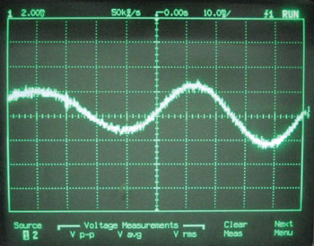
Figure 10 IF waveform of the proposed SSPR-SOM Doppler radar used as a motion detector.
Acknowledgment
This study was supported by a research grant from Kangwon National University. The authors would also like to thank Professor Yasuo Kuga of the University of Washington for help in the research.
References
- M. Fernandez, S. Ver Hoeye, L.F. Herran, C. Vazquez and F. Las Heras, "Design of High-gain Wide-band Harmonic Self Oscillating Mixers," 2008 Integrated Nonlinear Microwave and Millimeter-Wave Circuit Workshop Digest, pp. 57-60.
- D.H. Evans, "A Millimeter-wave Self-oscillating Mixer Using a GaAs FET Harmonic-mode Oscillator," 1986 IEEE MTT-S International Microwave Symposium Digest, pp. 601-604.
- S.A. Winkler, K. Wu and A. Stelzer, "A Novel Balanced Third and Fourth Harmonic Self-Oscillating Mixer with High Conversion Gain," 2006 European Microwave Conference Digest, pp. 1663-1666.
- O. Boric-Lubecke and V. Lubecke, "A Coherent Low IF Receiver Architecture for Doppler Radar Motion Detector Used in Life Signs Monitoring," 2010 IEEE Radio and Wireless Symposium Digest, pp. 571- 574.
- C.C. Hwang, J.S. Lee, H.H. Kim, N.H. Myung and J.I. Song, "Simple K-band MMIC VCO Utilizing a Miniaturized Hairpin Resonator and a Three-terminal p-HEMT Varactor with Low Phase Noise and High Output Power Properties," IEEE Microwave and Wireless Components Letters, Vol. 13, No. 6, June 2003, pp. 229-231.
- D.M. Pozar, "Microwave Engineering," 3rd Ed., John Wiley & Sons, Somerset, NJ, 2005.
- M.R. Tofighi and A.S. Daryoush, "A 2.5 GHz InGaP/GaAs Differential Cross-Coupled Self-Oscillating Mixer (SOM) IC," IEEE Microwave and Wireless Components Letters, Vol. 15, No. 4, April 2005, pp. 211-213.
- B.R. Jackson and C.E. Saavedra, "A Dual-Band Self-Oscillating Mixer for C-Band and X-Band Applications," IEEE Transactions on Microwave Theory and Techniques, Vol. 58, No. 2, February 2010, pp. 318-323.