

It’s quite well known that radar and radio systems are increasingly complicated with their continued improving range and resolution. As a result, system performance verification testing is expensive and technically challenging. Test capability must provide accurate and rapid results to match real-world situations in: Radar System Development, Verification, Qualification, Production, and Calibration scenarios.
The three common approaches to radar testing are: range testing, simulation, and channel replication. The strengths and weaknesses of these alternatives are well known, but some detail will help you in determining the best method for a particular application.
Range testing is probably the most comprehensive approach. It duplicates the real-world environment. Frequently used for final or system acceptance test, the range test can be conducted with actual targets or strategically located corner reflectors. This method is not well suited for development work that requires many tests over extended periods. The variable nature of the range environment also creates uncertainties in the test results. This uncertainty makes it difficult to be positive that a change in a test result is due to a design change or a change in the test environment.
Other drawbacks associated with range testing include cost, weather-related problems, health hazards, environmental restrictions, radiation regulations (FAA, FCC, etc.), security, and program delays.
Simulation is a great alternative to range testing. Simulations eliminate the cost and environmental issues associated with range testing. They aid in system development. The measurements are repeatable and consistent. One difficulty with simulations is that they require some knowledge of the radar system architecture to function correctly. It is difficult to create a universal simulator, or one with wide frequency bandwidth and dynamic range.
Propagation Path Replication (PPR) is a variation on the simulation approach. Like simulation, PPR testing can be done in a controlled laboratory environment, eliminating signal radiation, logistical problems, and delays associated with range testing. Propagation Path Replication reproduces the normal environment associated with the real-world radar application. This includes multipath (clutter), moving targets (Doppler), multiple targets, path loss, and delay.
The Propagation Path Replication approach is broadband (> 20 GHz instantaneous bandwidth), has minimal latent delay, requires no information about the radar system modes of operation, is expandable to include intentional and unintentional interferers, and provides more than 120 dB of dynamic range.
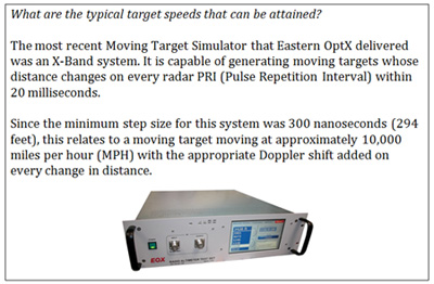
One broadband approach for PPR is based on optical fiber spools to build the target propagation path and multipath delays. Optical fiber is lightweight, low cost, rugged, and low loss. A typical 1U, 19-inch chassis can provide target distances up to 35 km. Moving target Doppler Generation is provided with a vector modulator and propagation loss, radar cross section, and system antenna gain are all incorporated into the loss model.
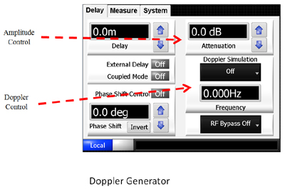
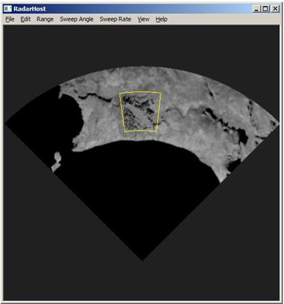
The typical Propagation Path Replication system Graphical User Interface (GUI) includes target distance and speed control, system gain settings, propagation loss factors, longitude / latitude target position input, and multipath selection.
The PPR approach can create moving target scenarios by coupling the variable delay with the Doppler generation. Scenarios begin with an initial target longitude, latitude, and altitude, a transit target speed, and a destination longitude, latitude, and altitude. Multiple scenarios may be stitched together to create a complete moving target test pattern.
Recent PPR Innovations
There have been three recent innovations in Propagation Path Replication:
- Increased phase stability
- Increased speed
- Full target path scripting
The first improvement, increased phase stability, determines the actual radar system base-line performance with greater accuracy. Since the test system stability is improved, there is greater visibility in the radar signal sensitivity and discrimination. This technique was achieved using special material processing and system stabilization.
The following plot shows PPR phase stability over a two-hour period for a 40 us delay at 3 GHz.
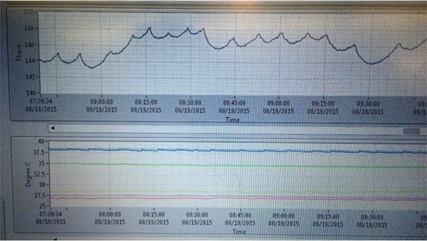
This represents almost 1000X (30 dB) improvement over conventional systems.
The next improvement provides an increase in target update speed from ~100 us to ~50 ns. The increase in speed allows the user to create faster targets with higher tracking accuracy. This higher speed is accomplished by first creating target path scripts. The scripts are then loaded, and into an FPGA (Field Programmable Gate Array) for high-speed execution.
Following is a sample script.
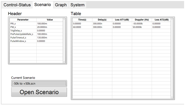
This script includes:
- Target distance (DELAY)
- Target velocity (Doppler)
- Signal loss (due to target distance and radar cross-section)
Radar signal characteristics such as pulse width and pulse repetition rate may be included so that the system may detect the radar pulses and set the target values in between radar pulses. This approach eliminates transition errors and offers better Doppler performance with an FPGA clock speed of ≈10 ns.
The following image shows the third performance enhancement: full path scripting:
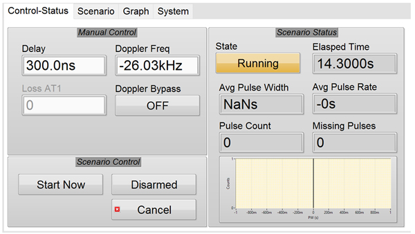
While manual setting may be selected using this screen, it will also display results of a loaded scenario during and after execution. A graph is also given for this scenario generator as shown in the following.

The blue trace shows the planned target distance while the red trace shows the target speed, both of which are functions of time. Note that target speeds may increase and decrease and the targets may change direction. Once the scenario begins the graph is updated with the actual values (target distance and speed) that overlay the scenario plan to provide a visual measure of the system accuracy.
 The Propagation Path Replicator has a long history as a valuable radar test tool, reducing the test cost and time, eliminating the need to radiate, and providing an accurate, real-world target generation.
Three recent improvements have made this technique the top solution for radar testing: phase stability, dramatic improvement in system speed (faster target update), and full target path generation.