

Bandwidth is being consumed everywhere, in electronic vehicles and by 5G cellular wireless communications networks. While it may be becoming thinner at lower frequencies, it is still available at higher frequencies, at millimeter wavelengths. These correspond to a range of 30 to 300 GHz, often starting at 24 GHz in vehicular radar systems, and many microwave circuit designers are faced with the task of moving higher in frequency and developing millimeter-wave printed circuit boards (PCBs). They need to design and fabricate the finer circuit features needed for the smaller wavelengths of millimeter-wave frequencies, making a transition from microwave to millimeter-wave frequencies. Higher frequency PCBs require a thoughtful choice of circuit materials well suited for millimeter-wave frequencies and circuit fabrication processes that support those higher frequencies. Part 1 of this blog will explore circuit material characteristics that make them best suited for millimeter-wave frequencies. Part 2 will examine high frequency structures and the fabrication processes that can help them do best at millimeter-wave frequencies.
Millimeter-wave PCBs were once considered esoteric or, at the very least, solely the foundations of military/aerospace applications. Large numbers of wireless communications users below 6 GHz and the large amounts of data they generate are congesting microwave frequency airwaves and cultivating strong interest in the use of higher frequencies. While the first four generations of cellular wireless communications networks have performed reliably at microwave frequencies, the Fifth Generation (5G) is looking to millimeter-wave frequencies for sufficient bandwidth for high speed, short-range data links. In addition to personal wireless communications, 5G networks will support countless sensors, identification, monitoring, and surveillance devices. And automakers are relying on Advanced Driver Assistance System (ADAS) equipment including short-range radars operating at millimeter-wave frequencies for safer vehicles. Demands are growing for millimeter-wave circuits and with them the need for dependable circuit materials.
Material Qualities
Circuit designers face numerous changes when making a transition from microwave to millimeter-wave frequencies. Wavelengths continue to shrink as frequencies rise, requiring finer circuit structures. Also, signal power—generating it and maintaining it—is typically less at millimeter-wave frequencies than at microwave frequencies, so that low circuit loss is a key circuit design goal. Without considering the type of circuit structure, such as microstrip, stripline, substrate integrated waveguide (SIW), or grounded-coplanar-waveguide (GCPW) transmission lines at millimeter-wave frequencies, circuit materials for millimeter-wave circuits should be considered for whether they have optimal basic qualities, such as dielectric constant (Dk) and dissipation factor (Df), for circuits and applications making a transition to higher frequencies. A circuit material’s Dk is related to the real component of the material’s complex permittivity while its Df or loss tangent is related to the imaginary component of the material’s complex permittivity. These and other essential circuit material qualities can provide invaluable insight into how a circuit laminate will perform at millimeter-wave frequencies compared to microwave frequencies.
For example, many applications, such as automotive radar systems, require consistent, stable signal phase at millimeter-wave frequencies, such as 77 GHz. A circuit material well suited for millimeter-wave circuits would leave no trace of its own on a circuit’s phase response or the way that signals propagate through its metal conductors. For this type of performance at millimeter-wave frequencies, a circuit material must have minimal change or variation in Dk value. Even small Dk deviations, if they can be accurately measured, can result in variations in signal propagation and phase through a millimeter-wave transmission line.
A circuit material’s Dk is typically determined by fabricating a reference circuit on the material under test and measuring phase for different lengths of transmission lines at different test frequencies. The test frequencies and the phase lengths of the transmission lines correspond to Dk values which are then associated with that dielectric material and thickness and that measured thickness of laminate metal.
For the small wavelengths of millimeter-wave signals, and depending upon the transmission-line format, circuit materials with low, stable Dk values (such as about 3.0) support many higher frequency circuits with minimal variations in signal phase. Variations in Dk within the material should be minimized to minimize signal phase variations. Again, the amount of impact that a circuit material’s Dk variations will have at millimeter-wave frequencies will depend upon the type of circuitry and transmission lines. Some circuit configurations are well suited for standard circuit fabrication processes but may not support all the small circuit features needed at millimeter wavelengths. A transition from microwave to millimeter-wave circuits represents a choice of circuit laminate as well as transmission-line technology for the best results.
Another basic circuit material quality to be considered when specifying a circuit material for the millimeter-wave frequency range is Df or loss tangent, often referred to as just its loss. Low Df values are usually associated with low Dk values and, as with Dk, low Df values are preferred for circuit materials to be used for millimeter-wave circuits. Similarly, as Dk variations can degrade a circuit’s phase response at millimeter-wave frequencies, a circuit material’s Df variations can impact a circuit’s amplitude response as a function of frequency, with loss increasing with increasing frequency. For any circuit at millimeter-wave frequencies, a choice in circuit technology should be part of a choice in circuit material since some transmission-line technologies will be less affected by variations in Dk and Df than others. However, as Part 2 of this blog will explain, some transmission-line technologies are better suited to handling the process variations that can be encountered when fabricating millimeter-wave circuits on even the best circuit laminates.
Several additional circuit material properties help guide specifiers to circuit laminates for millimeter-wave circuits. The surface roughness of the copper at the copper/dielectric interface of a laminate, can limit millimeter-wave circuit performance if excessive. The increased loss and variations in signal phase will depend on operating frequency and type of transmission line. For microstrip (Fig. 1), smoother copper is better: circuit laminates with rougher copper surfaces suffer increased conductor (insertion) loss and phase variations than the same dielectric materials and material thicknesses with smoother copper surfaces.

Fig 1. This cross-sectional view of a microstrip circuit exaggerates the roughness of the copper surface at the interface with the dielectric material.
For microstrip, the effects of copper surface roughness are greatest for thinner circuit materials (Fig. 2). The effects can be minimized with thicker dielectric materials, although doing so will increase the circuit sensitivity to dielectric losses for those microstrip circuits.
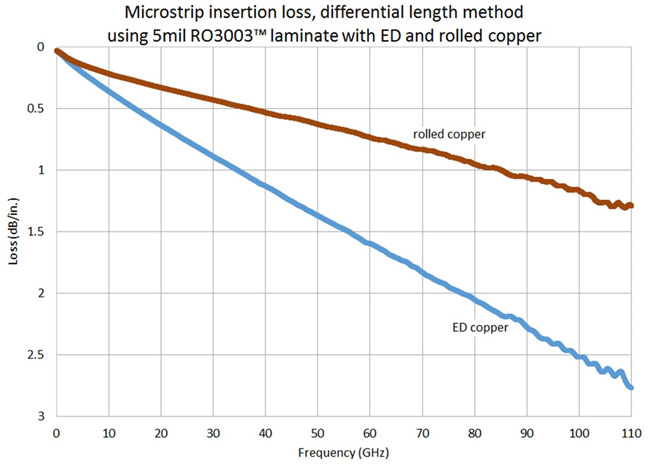
Fig 2. Measurements on 5-mil-thick RO3003™ laminates from Rogers Corp. show that differences in conductor types and copper surface roughness make differences in loss through 110 GHz.
Copper conductor surface roughness impacts millimeter-wave circuits especially as they are used for higher frequencies since the skin depth of an electromagnetic (EM) wave decreases with increasing frequency. The greatest degradation in amplitude and phase occurs when the skin depth of an EM wave is close to or less than the dimensions of the copper conductor surface roughness, generally the case at millimeter-wave frequencies. Circuit materials are available with different types of copper, each with its own amount of surface roughness. High profile copper is the roughest, with the greatest amount of impact on a millimeter-wave circuits loss and phase performance, while rolled copper is the smoothest, with the least amount of impact. In between, reverse treated (RT) copper and electrodeposited (ED) copper laminates provide surface roughness values that serve as midway points for their effects on loss and phase.
Rougher copper surfaces also result in a higher effective Dk value, or the Dk that a circuit “sees,” for a material, as does thicker copper with certain designs, such as GCPW. A higher effective Dk will slow the propagation of an EM wave, causing phase variations in millimeter-wave circuits and timing variations in high speed digital circuits. For that reason, the surface roughness and thickness of a copper laminate should be considered when a design is based on a circuit material with a particular effective or “design” Dk value, as the values of the copper thickness and its surface roughness, and variations in those values across the circuit material, can introduce unwanted performance variations especially at millimeter-wave frequencies. The effects of copper thickness and surface roughness are less for circuit materials with thicker dielectric materials than for those with thinner dielectric materials.
The next blog, the second installment of this two-part study on making the transition from microwave to millimeter-wave circuits, will review some of the transmission-line technologies used for millimeter-wave circuits and how they compare in terms of fabrication processes. Smart choices in circuit materials and transmission-line technologies can lead to practical, high performance millimeter-wave circuits.
For additional information on selecting circuit materials and transmission-line technologies for millimeter-wave circuits, this blog and its first part are based on a MicroApps presentation made by the author at the 2021 IEEE International Microwave Symposium (IMS) virtual event, “Designers Guide to the Transition from Microwave to Millimeter-Wave, when using PCB Technology,” 2021 IEEE IMS, virtual event, June 20-25, 2021.1
Do you have a design or fabrication question? Rogers Corporation’s experts are available to help. Log in to the Rogers Technology Support Hub and “Ask an Engineer” today.
References
1. John Coonrod, “Designers Guide to the Transition from Microwave to Millimeter-Wave, when using PCB Technology,” IEEE International Microwave Symposium, virtual event, June 20-25, 2021.