
The last decade has been marked by rapid development in the avionics integrated systems that have important advantages: Fewer units, smaller size, less weight, lower power use, reduced cable count, extensive built-in test equipment (BITE) and integrated maintenance features. This article describes different aspects of RF design of the L-band integrated systems.
Figure 1 illustrates existing L-band Traffic Surveillance Systems (TCAS, Transponder, UAT, ADS-B) and communication/navigation systems (DME, TACAN, GPS, JTIDS/MIDS). The Traffic Collision and Avoidance System (TCAS) located aboard a protected aircraft periodically transmits interrogation signals that are received by transponders located aboard other aircraft, here after referred to as target aircraft, in the vicinity of the protected aircraft. In reply to the interrogation signals, the target aircraft’s Transponder transmits a response signal. The TCAS equipment aboard the protected aircraft determines the range of the target aircraft in accordance with the round trip time between transmission of the interrogation signal and receipt of the response signal. Results are provided as displayed data and possibly traffic advisories about potential collision situations. The TCAS uses signals from directional antennas to determine the bearing from the host aircraft to a target (e.g., another aircraft). The TCAS operates on transmit frequencies in the 1030 ±10 MHz range and receive frequencies in the 1090 ±10 MHz range.
The Transponder is an airborne receiver-transmitter portion of air traffic control Radar Beacon System Mode-A and Mode-C interrogations as well as of Mode-S interrogations. The Transponder sends an identifying coded signal in response to a received interrogation from a ground-based radar station to locate and identify the aircraft. Reply signals from the Transponder are used to generate displays of the replying aircraft identification, position and altitude for air traffic controllers. The Mode-S function of the Transponder is used to transmit TCAS-related information between TCAS-equipped aircraft. The Mode-S Transponder consists of the Transponder receiver-transmitter, two omni-directional L-band antennas (top and bottom) and a control panel. The Transponder receives the uplink interrogation pulses at a frequency of 1030 MHz, and sends the downlink reply at 1090 MHz. Automatic Dependent Surveillance-Broadcast (ADS-B) provides real-time, fast update traffic information to pilots who have on-board traffic displays. For most pilots, graphic depiction of traffic is currently unavailable. With each aircraft’s ADS-B system (operating in ƒ = 1090 ± 1 MHz) that receives position reports from other aircraft in the vicinity, pilots will be able to determine not only the position of conflicting traffic, but will clearly see the traffic’s direction, speed and relative altitude. ADS-B is viewed as both a surveillance tool and a prime provider of pilot situational awareness. The system also broadcasts a radio transmission from the aircraft approximately once per second containing its position, velocity, identification and other pertinent information.
The Universal Access Transceiver (UAT) is a broadcast data link operating at 978 ±1 MHz. UAT is a transceiver system designed specifically to support the function of ADS-B. UAT is intended to support uplink broadcast data from ground stations. In addition to receiving and transmitting ADS-B signals from aircraft, the UAT datalink system is capable of uplinking and broadcasting data from fixed ground radar stations in two modes: FIS-B (Flight Information Services - Broadcast) mode and TIS-B (Traffic Information Services - Broadcast) mode. FIS-B data includes a wide variety of information, including weather broadcasts (graphical and text), airport status reports, temporary airspace restrictions and official Notices to Airmen called NOTAMs.

Figure 2 Frequency bands of different avionics L-band systems.
TIS-B data includes information about air traffic gathered from ground-based radar systems. The Distance Measurement Equipment (DME) provides position navigation information by measuring the line-of-sight distance between the aircraft and selected DME ground stations, additionally decoding the station identifier and calculating the rate of closure and time to reach a particular station. The DME operates on 252 one MHz-wide channel assignments in the range of 962 to 1213 MHz; each channel having an air to ground frequency assignment in the range from 1025 to 1150 MHz and a ground to air frequency assignment that is either in the range of 962 to 1024 MHz or 1151 to 1213 MHz. The Global Positioning System (GPS) is a United States Government system operated by the Department of Defense. The system provides an aid to radio navigation that uses precise range measurements from the GPS satellites to enable accurate position fixes to be determined anywhere in the world. The GPS L5 signal transmits and receives signals at 1176.45 MHz. The Joint Tactical Information Distribution System/Multi-functional Information Distribution System (JTIDS/MIDS) operates over 51 frequencies between 969 and 1206 MHz. Airborne platforms equipped with JTIDS/MIDS may have top and bottom mounted antennas. Figure 2 illustrates frequency bands of different avionics L-band systems; Table 1 shows the specifications of the L-band avionics systems.

Integrated L-Band Avionics Systems
The advantages of the integrated L-band systems (see Figure 1) include smaller size, less weight, lower power use, reduced cable count, extensive built-in test equipment (BITE) and integrated maintenance features. Conventional separate TCAS and Transponder systems require at least four antennas, ten cables, separate receivers and transmitters. Therefore, these systems are heavy, occupy a substantial amount of space and are very costly. The Integrated TCAS/Transponder system includes top and bottom combined antenna modules1,2 electrically connected to the TCAS/Transponder transmit/receive block to provide directional or omni-directional TCAS or Transponder radiation antenna pattern and directional TCAS and Transponder receive antenna pattern. The characteristics of typical airborne amplitude comparison and phase interferometer directional finding (DF) systems are summarized in referenced material.3,4
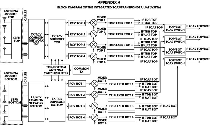
The conventional TCAS amplitude monopulse system as compared to the phase monopulse system is relatively simple and cost effective, but also relatively inaccurate. To improve a bearing accuracy of the amplitude monopulse system, amplitude calibration and antenna look-up tables (LUT) are used. Appendix A illustrates the top level RF block diagram of the integrated TCAS/Transponder/UAT system. An option to use a frequency triplexer is provided to allow sharing of a single antenna between the TCAS/Transponder and the UAT unit. The TCAS, Transponder and UAT transmitters are integrated in the common transmitter block. The top/bottom antenna switch/splitter has the following functions: Alternate coupling of the TCAS transmitter with the four top or the four bottom directional antenna inputs to generate format interrogation signals; coupling of the Transponder transmitter with the top or bottom omni-directional antenna during the Transponder transmit mode for transmitting reply signal; coupling of the UAT transmitter and receiver with the top or bottom omni-directional antenna.
Generally, L-band TCAS, Transponder and DME systems employ separate antennas, receivers and transmitters. Thus, each aircraft may include a top and bottom TCAS antenna, top and bottom Transponder antenna, and bottom DME antenna. The total number of TCAS, Transponder and DME antennas of one aircraft is at least five: Top and bottom TCAS antennas, top and bottom Transponder antennas, and one bottom DME antenna. The total number of cables between antennas and the transmit/receive network is at least 11: Eight cables for the top and bottom four-monopole TCAS antennas, two for the Transponder top and bottom antennas, and one for the bottom DME antenna. The main disadvantages of these separate systems are high complexity, cost, size and weight. There are possibilities of an integrated TCAS/Transponder/DME system. Sharing a common antenna between the TCAS, Transponder and DME systems in an aircraft may be desirable to minimize antenna installation cost and complexity.
In the integrated TCAS/Transponder/ADS-B system, TCAS equipment that is capable of processing ADS-B messages may use this information to enhance the performance of TCAS, with techniques known as “hybrid surveillance”. As currently implemented, hybrid surveillance uses reception of ADS-B messages from an aircraft to reduce the rate at which the TCAS equipment interrogates that aircraft. The ADS-B messages will also allow low cost technology to provide real time traffic information in the cockpit for small aircraft. ADS-B is used only to identify aircraft that can be safely interrogated at a lower rate. In the future, prediction capabilities may be improved by using the state vector information present in ADS-B messages. Also, since ADS-B messages can be received at a greater range than what TCAS normally operates at, aircraft can be detected earlier by the TCAS tracking algorithms.

Figure 3 Block diagram of integrated transponder/DME/UAT/ADS-B system.
The integrated Transponder/DME/UAT/ADS-B system (see Figure 3) provides low cost, smaller dimensions and weight and greater reliability. The top RCV channel provides receiving of the Transponder, UAT and ADS-B signals while the bottom RCV channel is used for receiving of the Transponder, UAT, ADS-B and DME signals. In the bottom RCV, the diplexer splits the broadband DME signals from the Transponder, UAT and ADS-B signals. For this combined system, cost is the dominant factor. This combined system requires a multi-channel receiver front-end, which makes allowance for, on one hand, a large number of receiving channels each with a large dynamic range, and on the other hand, low cost, small volume, low weight and low dissipation of these receiving channels. The combined system receiver consists of three channels (1090 MHz ADS-B, 1030 MHz Transponder and 978 MHz UAT) assigned to the top antenna and four channels assigned to the bottom antenna—the same three channels identified above plus the DME channel (960 to 1215 MHz). The same antenna (blade types) can be used for DME, Transponder, UAT and ADS-B. A common front-end receiver should be designed to satisfy different sensitivities or minimum trigger level (MTL) (see Table 1) for the Transponder: -74 dBm; for DME RCV: -85 dBm; for UAT RCV: -93 dBm; and for ADS-B: -84 dBm. To satisfy these requirements the combined integrated front-end receiver should provide different subsystem channel sensitivities. Depending on the UAT equipment class of the installation, the UAT will require either one or two antennas.
Existing L-band systems (TCAS, DME) can provide a redundant navigation system alongside the GPS during the transition to a sole-means GPS national airspace system. TCAS provides the data link for differential GPS corrections through the Mode-S Transponder. With Mode-S being proposed as a national aeronautical data link system, the system may be an effective GPS for a large segment of the aviation community. As the FAA moves to a sole-means GPS NAS, the need for the existing radio-navigation infrastructure will diminish.5 The total navigation suite would consist of a GPS receiver and a DME-DR system.
RF Design of Integrated System
RF circuits of the avionics integrated systems have some advantages, including low cost; low volume and weight; common antenna module; common transmitter; and single multi-channel receiver. The combined RF systems require a multi-channel receiver front-end, which makes allowance for, on one hand, a large number of receiving channels each with a large dynamic range, and, on the other hand, low cost, small volume, low weight and low dissipation of these RCV channels.
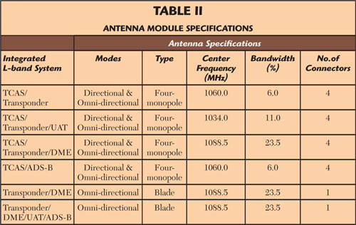
Table 2 illustrates antenna module specifications for different integrated avionics L-band systems. The antennas of the integrated systems including TCAS can be operated in two configurations. The top antenna module must provide the directional and the omni-directional modes. The bottom antenna module may be either likewise directional/omni-directional or sometimes omni-directional only to reduce cost. In integrated systems without TCAS (Transponder/DME; Transponder/DME/UAT/ADS-B), the typical antenna is a vertically polarized metal blade with one BNC or TNC connector. Most of the L-band blade antennas are thin blades about a quarter wavelength in height due to aerodynamic considerations.
The conventional TCAS phase array antenna produces a vertically polarized directional or omni-directional radiating pattern when driven by excitation signals of appropriate phase. Each antenna element (monopole) is independent of the others and is connected to the transmitter/receiver through its own coaxial connector. This special beam steering network provides for different positions of the antenna pattern in the polar system. In an integrated system with TCAS, a multi-monopole antenna array is required. An antenna array configuration depends on the type of system used—phase monopulse system vs. amplitude monopulse system. Due to the poor bearing accuracy of the amplitude monopulse systems, the TCAS requires special amplitude calibration and antenna LUT to satisfy the bearing accuracy requirements.

Figure 4 Block diagram of amplitude monopulse antenna module (a) and broadband antenna module (b).
For the amplitude monopulse system, the special antenna switched beam forming network (SBFN) with a relatively narrowband switched 0/180-degree phase shifter (see Figure 4a) is used.6-9 The L-band antenna module provides the directional antenna patterns by using a special SBFN that includes a 44 hybrid matrix. Four 90-degree hybrids are serially interconnected to form the 44 hybrid matrix. Ports 5, 6, 7 and 8 of the hybrid matrix are connected to antenna monopoles A1, A2, A3 and A4, respectively, and the other four ports 1, 2, 3 and 4 are connected to the integrated unit by cables. The eight-port hybrid matrix is used in the SBFN to provide equal amplitudes and specific relative phases for the four antenna monopoles. The directional transmit mode is implemented by the alternate activation of input ports 1, 2, 3 and 4 of the SBFN while the switched phase shifter provides 0 degree phase shift. Each of the four antenna module inputs corresponds to a beam in one of four directions: Front (F), right (R), aft (A) or left (L). During the omni-directional transmit mode only, one terminal (2) is activated while the switched phase shifter is controlled to be at the 180-degree position. During the receive directional mode, which provides bearing measurement, all four of the antenna connectors are monitored while the switched phase shifter is at the 0-degree position. The relative signal intensity from four SBFN ports 1, 2, 3 and 4 show azimuth direction of a selected object according to the special bearing algorithm (index) and antenna LUTs.6 This RF network can be used for the narrowband integrated systems: TCAS/Transponder; TCAS/Transponder/UAT or TCAS/Transponder/ADS-B.
The main disadvantage of the amplitude monopulse antenna module (see Figure 4a) is the difficulties of the omni-directional mode for the integrated systems including DME due to their wider bandwidth (BW=23.5 percent). The narrowband switched 0/180-degree phase shifter limits the bandwidth of the integrated system. Figure 4b illustrates the broadband antenna module block diagram1 without the narrowband switched phase shifter. This antenna module can be used for the relative broadband integrated systems (TCAS/Transponder/DME or TCAS/Transponder/UAT). During the transmit omni-directional mode (for Transponder, DME), the transmit signal passes from the integrated unit through one cable, terminal 4, SPDT switch and four-way divider to the four monopoles. The broadband divider can be implemented using conventional Wilkinson dividers or directional couplers. The four-way divider and BFN are located close to the antenna monopoles to minimize phase and amplitude imbalance between the four terminals of the antenna module. The TCAS directional transmit mode is implemented by the alternate activation of input ports 1, 2, 3 and 4 of the BFN. The position of the antenna pattern depends on which input is activated. During the receive directional mode that provides bearing measurement, all four of the antenna connectors are monitored, and receive signals pass through the four SPDT switches and BFN to the integrated broadband unit.
The novel four-folded monopole antenna is described in the references.6-8 This antenna can be used for integrated avionics systems including TCAS. The most important future of this antenna array is the possibility of both directional and omni-directional modes, good electrical performance, low profile and weight. As a result of using this antenna configuration with the SBFN, the integrated systems TCAS/Transponder/DME and TCAS/Transponder/UAT includes the two antenna modules (top and bottom), eight cables, and eight receiver channels instead of five antennas, 11 cables, and 11 receiver channels of the existing three separate systems. The antenna module performance depends on antenna configuration, beam forming network, switching circuit and matching network.
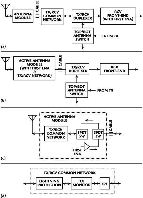
Figure 5 Block diagram of conventional RF module (a), active antenna module (b), RCV network (c) and typical RF TX/RCV common network of combined avionics systems.
Figure 5a illustrates the block diagram of the conventional top level RF module. Consider the specific circuits of this block diagram: Antenna module, common TX/RCV network, duplexer, front-end receiver and switch.The conventional TCAS antenna modules are passive devices, where the front-end receivers connected after the lossy cables have low sensitivity and therefore an aircraft range measurement is limited. The position of the first LNA in the receiver front-end block (Figure 6a) limits the minimum noise figure (maximum sensitivity) due to insertion loss of the circuits before the LNA. For example, according to the reference,10 the existing avionics cable has a maximum loss of 3 dB. Also, the cable matching might be up to VSWR = 1.7 that lowers the electrical performance of an antenna SBFN. To eliminate these disadvantages in high sensitivity avionics systems, an active antenna module with an LNA can be used. Figures 5b and 5c illustrate top level block diagrams of the active antenna module and RCV network.
Figure 5d illustrates the typical RF TX/RCV common network of combined avionics systems that includes the following blocks: Lightning protection, TX monitor and low pass filter (LPF). The TransGuard Transient Voltage Supressor provides protection of the front-end receiver from voltage transient caused by lightning. In the LPF, all frequencies of TX and RCV below a set frequency are selected, and all frequencies above this same set frequency are eliminated. Usually, in avionics systems, the LPF is the stepped-impedance circuit that has poor electrical performance due to relatively low Q-factor of the microstrip line. A lower loss LPF can be implemented using a combination of microstrip and suspended substrate lines.10 Reduction of size and harmonic signals can be realized in the LPF with the defected ground structure (DGS).12,13
Most L-band avionics systems have a common transmit/receive antenna, which is why the transmitter/receiver network should include an RF duplexer. An RF transceiver duplexer connects the single antenna to the transceiver. There are three main types of duplexers in common use.14 The first duplexer consists of an SPDT transmit/receive switch/limiter. The second type includes a ferrite circulator, and the third includes a ferrite circulator and a transceiver protector. The comparison13 shows that the duplexer with a circulator has several disadvantages as compared to the TX/RCV switch. Its only advantages are good TX peak power and protection of TX from unwanted reflected synchronous signals. During the transmit mode, the switch provides sufficient isolation in the receiver port to protect the receiver front-end from damage. During the receive mode, the switch isolates the transmitter from the antenna and connects it to the receiver.
The transceiver protector in L-band avionics integrated systems provides: 1) protection of the receiver from large input signals while allowing the receiver to function normally when these large signals are not present; and 2) protection of the transmitter from signals reflected from the receiver due to receiver and antenna mismatch. In the duplexer with a circulator, the transmitter power may leak into the receiving system due to non-ideal circulator isolation, antenna port reflection paths, as well as to mutual coupling between adjacent antenna array elements. This can cause such problems as saturation, gain compression of the receiving system and increased FM-AM noise. Also, sometimes unwanted and potentially damaging high power signals from nearby systems (non-synchronous signals) received by the antenna pass to the receiver. There are three types of transceiver protector configurations: Active limiter, passive limiter and quasi-active limiter.14 Several functions of a transceiver protector can be combined.

Figure 6 Multifunctional RF schematic.
Figure 6 illustrates the multifunctional RF schematic with the following three functions: Transmit-receive switching (duplexer function), limitation of the strong parasitic RF signals and self test. The switching function is to connect the antenna to the transmitter in the transmit mode and to the receiver during the receive mode. This switch includes the series shunt circuit with diodes D1, D2 in the transmit pass, and the series shunt circuit with shunt diodes D3, D4 in the receive path. During the transmit mode the switch should have sufficient isolation in the receiver port to protect the receiver from parasitic signals. The limiting function provides protection of the LNA and the mixer from strong RF parasitic signals. While the system is not powered, protection from strong outside parasitic RF signals is provided by limiter diode D3 and by limiter diode D4 with Schottky diode D5, commonly referred to as the cleanup stage.11 While the system is powered, the first and second limiter diodes are active (forward biased) and provide protection of the receiver front-end from the TX leakage. The self-test function can be implemented by the combination of a noise source network and an RF power monitor circuit for control receiver elements. The noise network is located after the switch/limiter network because a noise diode should be protected from the strong parasitic signals. In the self-test mode, when the network (see Figure 6) is not powered, noise diode D7 generates noise for receiver testing and drive PIN diode D6 is forward biased. As a result, the noise signal generated by diode D7 is coupled through diode D6 and applied to the receiver for the receiver self test.
All combined integrated systems have top and bottom antenna modules that are switched by the special top/bottom antenna switch/splitter. The peak power transmitted from the selected antenna should exceed the power transmitted from the non-selected antenna by at least 20 dB. To satisfy this requirement the top/bottom antenna diversity switch should provide at least 20 dB of isolation. The single PIN diode in the switch transmit path can provide for this requirement, but to satisfy the existing manufacture tolerances and environmental conditions the two PIN diodes in the transmit path may be necessary. The conventional shunt diode switch with the quarter-wave lines between diodes11 has a narrow frequency band (~10 percent) and can be used in the narrowband integrated systems (see Table 1). For the wideband integrated systems, the top/bottom switches should be modified. The broadband switches are implemented with the additional transformers,15 series PIN diodes, or series-shunt PIN diodes (see Figure 6).
There are two possible configurations in the superheterodyne receiver front-end. The placement of the LNA before the bandpass filter (BPF) gives a better receiver cumulative noise figure, but leaves the LNA unprotected from the out-of-band interfering signals. Also, the BPF placed at the LNA’s output rejects the image noise that is created by broadband noise from the LNA. This configuration of the front-end receiver can be improved by the implementation of good rejection of the input LPF and an additional quasi-active and/or active limiter to provide better rejection from the out-of-band interfering signals. If the BPF is the first block followed by the LNA (see Figure 6), noise power will be directly converted into the IF band without filtration between the LNA and the mixer. In this case, cumulative noise figure is higher than the first block diagram, but the LNA is protected from unwanted interfering signals. Placing the BPF before the LNA limits the bandwidth of the input spectrum to minimize intermodulation and spurious responses.
An electrically tunable preselector is a key element in the integrated systems including DME (TCAS/Transponder/DME, Transponder/DME/UAT/ADS-B) (see Figure 3). The main purpose of the DME tunable preselector is the highly selective response to prevent large off-channel signals from overloading the receiver front-end and degrading sensitivity. To minimize receiver noise figure, the RF preselector filter is split into sections separated by an LNA.11 The first two-pole filter before the LNA prevents undesirable signals from over-driving the LNA. The second three-pole filter placed after the LNA provides selectivity against receiver image and spurious frequencies. The three-pole filter placed after the LNA has a negligible effect on the overall preselector input NF. The passband of the tunable filter should be at 20 MHz, securing 10 times the reduction of noise and interference in the DME 960 to 1215 MHz frequency range. The electrically tunable BPF11 consists of the suspended substrate resonators, which are grounded at one end, high Q-factor GaAs varactor diodes, and lumped-element loading capacitors between the other end of each resonator and ground plane.
A diplexer/triplexer is an important component for channel separation in receiver channels of combined systems. A diplexer/triplexer provides isolation between receive channels by assigning a different frequency band to each channel. Usually, the minimum and maximum attenuation in the passband should be different by no greater than 0.2 dB. The VSWR produced by the diplexer/triplexer at the unit port, when the other ports are terminated in a 50 ohm load, should not exceed 1.3:1 for frequencies within the passband. A diplexer/triplexer should provide a minimum isolation of 40 dB between unit ports. Triplexers (see Figure 3 and Appendix A) can be used for separation of three output IF channels. A triplexer is formed by connecting three IF bandpass filters. Note that each filter can be designed individually to yield the desired passband before combining the three into a triplexer. Conventionally, design of a triplexer comprises two steps. The first step is to design useable IF filters; the second step is to combine the designed filters together by using the matching network.
An RF network of integrated systems can include two-, three- or four-way splitters. The following electrical parameters of a splitter are significant: Insertion loss, isolation, matching and intermodulation distortion. In transformer splitters with ferrites, intermodulation distortion is sometimes a critical issue. Distortion is caused by saturation of the transformer, usually of the toroidal type, especially at the high frequency end. Also, most transformer splitters require external components (resistors, capacitors) to provide acceptable splitter performance and a reduction in package size. A low-cost N-way splitter can be implemented with the Wilkinson power divider,11 which provides matching of all ports, low loss and acceptable isolation between output ports. The simplest Wilkinson divider consists of two segments that have the electrical length Θ=2πl/Λ0=90° or the physical length l= Λ0/4 (Λ is the mid-band guide wavelength) and lumped resistor R between the outputs of these segments. The conventional L-band Wilkinson divider is relatively large. To reduce size, the Λ0/4 segments of the divider can be substituted with an equivalent lumped element circuit.10
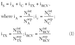
In integrated aircraft system applications, the trade-offs between physical and electrical properties are important design considerations. Trade-offs pertain to the following attributes: Electrical performance, cost, size and weight. The integration quality of the L-band avionics systems can be characterized by the integration index. The system integration index IS is determined by the ratios of the number of antennas NintA, cables NintC, transmitters NintTX, and receivers NintRCV of the integrated system to the number of antennas NsepA, cables NsepC, transmitters NsepTX and receivers NsepRCV of the individual (separate) systems (iA, iC, iTX and iRCV):
For the TCAS/Transponder/UAT/DME integrated system, the system integration index is
Is=2/7 +8/13+1/4+8/13=1.5 (2)
The RF circuits of the integrated avionics systems can be described by the circuit integration index:

where Sa, Sp, Sc, Sƒ are normalized areas of active devices, passive components, control devices and free space, respectively. The real circuit integration index Icir of existing L-band systems is between 1.05 and 1.4. The structure of a compact RF circuit can be implemented as multilayer design, three-dimensional design, or vertical-horizontal design.11 The total integration index is
IΣ=Is×Icir (4)
The minimum integration index IΣmin is optimal and indicates the smallest physical dimensions with acceptable electrical performance and reliability.
References
1. L.G. Maloratsky, et al., “Combined Aircraft TCAS/Transponder with Common Antenna System,” United States Patent No. 7,436,350, October 14, 2008.
2. D. Kutman, et al., “Multifunctional Aircraft Transponder,” United States Patent No. 6,222,480, April, 2001.
3. “Signal Sorting Methods and Directional Finding,” http://www.phys.hawaii.edu/~anita/web/parework.
4. M.P. Murphy, “Hybrid Amplitude/Phase Comparison Directional Finding System,” United States Patent No. 5,541,608, July 30, 1996.
5. D. Gebre-Egziabher, et al., “DME Based Area Navigation Systems for GPS/WAAS Interference Mitigation in General Aviation Applications,” www.//waas.stanfold.edu/~wwu/papers/gps/PDF/demozdme.pdf.
6. L.G. Maloratsky, “Analyze Bearing Accuracy of a Monopulse System,” Microwaves & RF, Part 1, March 2009; Part 2, April 2009.
7. L.G. Maloratsky, et al., “Aircraft Directional/Omnidirectional Antenna Arrangement,” United States Patent No. 7,385,560, June 10, 2008.
8. L.G. Maloratsky, “Switched Directional/Omnidirectional Antenna Module for Amplitude Monopulse Systems,” IEEE Antenna Magazine, October 2009.
9. L.G. Maloratsky, “Switched Beam Forming Network for an Amplitude Monopulse Directional and Omnidirectional Antenna,” United States Patent No. 7,508,343, March 24, 2009.
10. “Aeronautical Radio Inc., ARINC Characteristics 735A,” January 15, 2003.
11. L.G. Maloratsky, Passive RF and Microwave Integrated Circuits, Elsevier, 2004.
12. D. Ahn, et al., “A Design of the Low-pass Filter Using the Novel Microstrip Defected Ground Structure,” IEEE Transactions on Microwave Theory Techniques, Vol. 49, January 2001, pp. 86-93.
13. J. Chen, et al., “Low-pass Filter Design of Hilbert Curve Ring Defected Ground Structure,” Progress in Electromagnetic Research, PIER 70, 2007, pp. 269-270.
14. L.G. Maloratsky, “Transceiver Duplexer Design Considerations,” Microwave Journal, Vol. 51, No. 10, October 2008, pp. 68-86.
15. “Broadbanding the Shunt PIN Diode SPDT switch,” Hewlett Packard, Application Note 957-1, 1996.
Leo G. Maloratsky received his MSEE degree from the Moscow Aviation Institute and his PhD degree from the Moscow Institute of Communications in 1962 and 1967, respectively. Since 1962, he has been involved in the research, development and production of RF and microwave integrated circuits at the Electrotechnical Institute, and was Assistant Professor at the Moscow Institute of Radioelectronics. From 1992 to 1997, he was a Staff Engineer at Allied Signal. From 1997 to 2008, he was a Principal Engineer at Rockwell Collins where he worked on RF and microwave integrated circuits for avionics systems. He joined Aerospace Electronics Co. in 2008. He is the author of four monographs, one text-book, over 50 articles and 20 patents.