
In most fields today, electronic devices must meet strict certification requirements to ensure that humans are not exposed to excessive levels of radiated energy. If sufficiently high levels of power, quantified as the Specific Absorption Rate (SAR), are dissipated in human tissue, the result could be tissue heating and damage. Should a device that has reached the prototyping stage fail to pass SAR certification, a redesign will be required, costing both time and money. Through advanced software tools, designs can be iterated and validated for compliance, ensuring a good product before any prototypes are built. To adequately analyze this type of design, a fully three-dimensional approach for simulating the propagation of electromagnetic fields is required.
The SAR analysis for an MRI system, presented in this article, is based on the XFDTD® product from REMCOM Inc., which utilizes a finite-difference, time-domain (FDTD) method. In FDTD, the geometry under consideration is discretized into small block-shaped voxels. This approach works well with complex electronic devices and also preserves the configuration of the tissues within the human body. It has been recognized as the preferred method for making SAR calculations1 and has been widely used in a variety of applications.
XFDTD Use for MRI
In magnetic resonance imaging (MRI) systems, the field propagation and distribution in the human patient is important for good image quality in addition to the safety requirements. These quantities are difficult to measure in living human subjects, so simulation has become a useful method for research in the MRI field. As far back as 1998, researchers at the Center for NMR Research at Penn State College of Medicine used simulation to determine SAR and B1 fields from birdcage coils at several frequencies in realistic human head models. Studies have done similar work to investigate the field homogeneity and SAR in higher frequency MRI systems and with different coil configurations. For example, in 2003 DeMeester6 compared using body and head transmit coils to determine which gave lower SAR while still producing an acceptable B1 field. In fact, researchers developing MRI systems have used simulations to:

• Study and improve coil and shield designs7–9
• Find optimum transmit and receive arrays and waveforms to improve homogeneity9,10
• Investigate issues of dielectric resonance12–15
• Study the impact of metallic implants such as wires16 and electrodes for electroencephalography (EEG) recording17 on SAR
In addition to SAR, the temperature rise in the tissues is of particular interest, since it is the heating of tissues that causes the damage. Evaluation of the power absorbed in SAR does not take into account the cooling effects by blood flow and air movement. Work by Collins, et al.18 describes a technique to compute the temperature rise caused by absorbed power in the form of SAR. This technique, based on the Pennes bio-heat equation, can be achieved through simulation provided the software includes the appropriate thermal module, such as the one recently added to XFDTD.®
A continuing advance in simulation technology has allowed researchers to investigate extremely challenging problems. For instance, recent use of the XFDTD software included an MRI system, involving complex imaging devices made of arrays of elements with adjustable magnitude and phase such as the case19 where an 80-element coil made of five vertical elements in 16 columns is simulated on a human head (see Figure 1).
The importance of simulations can be summed up by the comments of Christopher Collins of the Center for NMR Research at Penn State College of Medicine, who attributes the use of the XFDTD product in particular as “a valuable tool in the field of MRI for applications ranging from ground-breaking fundamental discoveries and demonstrations to engineering and safety assurance. It is now something of an industry standard in our field.”
Human Body Data
In simulations involving MRI systems, a detailed dataset of the human body tissues is necessary for accurate results. These detailed datasets are available as meshes (available from REMCOM) based on the scans from the Visible Human male and female projects. These meshes are available in resolutions as fine as one millimeter, although the data may be rescanned in the software to any necessary voxel size. The highest resolution meshes contain 39 distinct tissues including 24 tissues in the head.
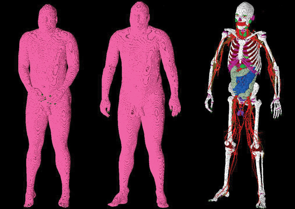
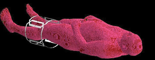
The original Visible Human data that is available for the XFDTD product has the body in a supine position with the arms crossed over the body. Unfortunately, this position is inappropriate for some MRI applications and will not yield SAR results that correspond with the MRI system’s actual use. Therefore, it is critical that researchers are able to manipulate the data including the re-positioning of the body into more desirable poses (see Figure 2). At left is the data in the original position, while at right is the data after processing by Varipose. The data is shown with all tissues present and again with the outer layers (skin, fat, muscle) removed to reveal the internal structure. All the limbs on the body, including the fingers, may require repositioning. It is also important that the internal tissue connections are maintained during repositioning in order to ensure continuity.
To improve the simulation speed, it may also be desirable for the body data to be cropped to include only those parts of interest for a particular application, such as separating the head or arm into a file of its own. An example of a commercial tool with the ability to manipulate the body model data is a separate product from REMCOM known as Varipose.®
MRI Coil Simulation
One area where the use of simulation tools can provide significant cost and time savings is coil design. Engineers making coil designs need to tune the coils by applying appropriately placed capacitors to get a resonance at the desired frequency. Using a prototyping approach, this can lead to several expensive models being built until proper values for the capacitors are found and the coil is tuned at a high level of Q. With simulation, the coil can be tuned with a few simple steps.
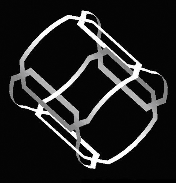
While whole body simulations with a large MRI coil (such as the one shown in Figure 3) can be computed, a simple coil example will be performed here to demonstrate the technique. An example of a four-element coil is shown in Figure 4, where identical coil elements are placed with a slight overlap. This coil measures approximately 280 mm in diameter with a length of 250 mm and may be placed over a knee for imaging. Here, it will be tuned for use at 64 MHz. This coil and tuning approach were generously provided by Fahad Alradady of MR Medical Solutions of Pittsburgh, PA.
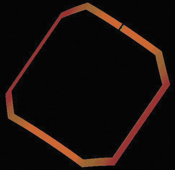
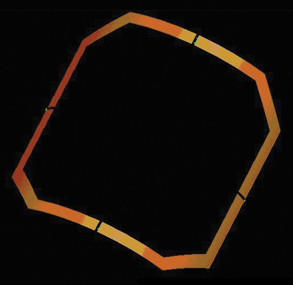
To begin the tuning process, start with a single coil element, as shown in Figure 5. A single cut is placed in the coil and a parallel combination of a voltage source and a wisely chosen capacitor are placed in the gap. For this case, a capacitor value of 7 pF was chosen. Although this coil is designed for receive-only use, by reciprocity it can be simulated in transmit mode for tuning. The coil is simulated with a broadband input of a Gaussian pulse to find the series resonance of the base coil.
Following the simulation, the return loss for the coil is plotted on a Smith chart, shown in Figure 6, to find the resonant frequency of the coil. The resonance is located at the point where the return loss is purely real, at approximately 68.5 MHz, which is slightly above the desired 64 MHz for the coil. With the resonant frequency value and the applied capacitance of 7 pF, the inductance of the coil structure can be computed. This is done by first computing the reactance due to the capacitor as
Since at resonance the inductive reactance will equal the negative of the capacitive reactance, the inductance of the coil loop may be computed as
Since the desired frequency for the coil is 64 MHz, and the inductance of the loop is known, the inductive reactance at 64 MHz may be found and then from this value the necessary capacitance may be computed to resonate the coil. This is done by first computing the reactance at 64 MHz for the coil inductance, or

To resonate the coil, the capacitive reactance must equal the negative of the inductive reactance, so the required capacitor value may be found as

To best resonate the coil at 64 MHz, the capacitance value should be distributed around the loop. The number of divisions of the capacitance should be based on the wavelength of the signal. In human tissue, the wavelength will be approximately 50 cm, so four gaps around the loop are determined to be appropriate to properly distribute the capacitance. Since the total capacitance needed to resonate the loop was found to be 8 pF, each elemental capacitance, connected in series, should be set to 32 pF. The resulting coil with the four capacitances attached is shown in Figure 7.
The coil with the four capacitive elements is simulated again with a broadband Gaussian pulse to determine the resonant frequency. The resulting return loss is shown in Figure 8 where the resonance can be seen to have shifted to the desired 64 MHz. At this point, a single coil has been tuned. This procedure of cutting gaps and adding capacitors should be performed for the other three elements of the total four-element coil.
In order to minimize coupling between the elements, a tank circuit is added at the feed point capacitor by adding an appropriate inductor to form a high impedance at 64 MHz making the coil seem invisible to the adjacent elements. Once this is done, the full coil is ready to be simulated at the design frequency to determine the quality of the field distribution. Following a simulation with a sinusoidal input at the desired 64 MHz, the magnetic field and magnetic flux density distributions across the center of the coil may be observed. A properly designed coil should give a homogeneous field across the coil and have nulls in the field centered between the coil overlaps.
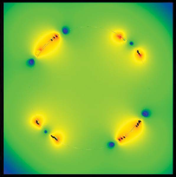
The resulting magnetic field through the center cross-section of the coil, shown in Figure 9, indicates that the coil is still not perfectly tuned. A well-tuned coil will have a strong null in the magnetic field between the coil elements. This null is visible in the upper right and lower left hand corners where a low field value (single blue dot) may be seen between the two coil elements, indicating minimal coupling. In the upper left and lower right hand corners, there is still some coupling between the adjacent coil elements, which is disturbing the magnetic field distribution and producing nulls at the outer edges of the elements. To reduce the coupling, the spacing between the elements requires some adjustment to make the field more homogeneous.
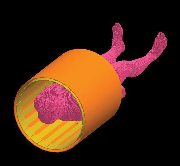
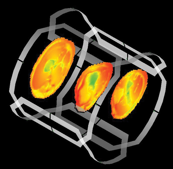
After the coil is properly tuned, a simulation of the loaded coil in use on a leg may be performed. The positioning of the coil is shown in Figure 10, where the knee is centered in the coil. The actual simulation is performed on a section of the leg in the vicinity of the coil. Note that the coil may need further tuning once it is under loaded conditions. This step is not discussed here, but it would involve optimizing the return loss when the leg is present in the coil. The resulting SAR distribution through the leg may be computed and observed to ensure that the device is within design specifications. The SAR in several leg sections is shown in Figure 11. In addition to the values shown here, the temperature rise in the tissue resulting from the SAR, the rotating B fields (B+/B–), the electric fields and the currents in the simulated geometry may also be displayed.
Conclusion
Research and development of MRI systems requires powerful software tools to evaluate and optimize designs. For a number of years, researchers in the MRI area have made use of FDTD software for computing the fields internal to the body, which are nearly impossible to measure experimentally and to design structures such as coils. The simulation procedure allows the coil designer to get quick feedback on the performance of the device, without the time or cost of producing numerous prototypes. The further ability to simulate the structure in practical use, such as the coil around a body part, permits the designer to optimize the device under loaded conditions and ensure that the regulated limits such as SAR are within thresholds. Improvements in software accountability for actual human body characteristics (such as heat transfer due to blood flow) provides enhanced accuracy with the capability of supporting body data re-positioning and cropping to ensure more accurate simulations, while reducing simulation time by restricting the analysis to just the areas of interest.
References
1. K. Chan, R.F. Cleveland Jr. and D.L. Means, “Evaluating Compliance with FCC Guidelines for Human Exposure to Radio-frequency Electromagnetic Fields—Additional Information for Evaluating Compliance of Mobile and Portable Devices with FCC Limits for Human Exposure to Radio-frequency Emissions—Supplement C (Edition 97-01) to OET Bulletin 65 (Edition 97-01), December 1997, Office of Engineering and Technology, Federal Communications Commission, Washington, DC.
2. C.M. Collins, S. Li and M.B. Smith, “SAR and B1 Field Distributions in a Heterogeneous Human Head Model Within a Birdcage Coil,” Magnetic Resonance in Medicine, Vol. 40, No. 6, 1998, pp. 847–56.
3. Z. Zhai, G. DeMeester, S. Shvartsman and M. Morich, “FDTD Calculations of B1 Field and SAR for 3T Whole Body Coil,” Proceedings of the International Society on Magnetic Resonance in Medicine, Vol. 10, 2002.
4. S. Shvartsman, Z. Zhai, G. DeMeester and M. Morich, “FDTD Calculations of Induced E-field in a Cylindrical Z-gradient Coil,” Proceedings of the International Society on Magnetic Resonance in Medicine, Vol. 10, 2002.
5. Y.C. Ryu, G.L. Khym, S.H. Ryu, B.Y. Choe and C.H. Oh, “Calculation of E-M Field Intensity and SAR for 3.0 Tesla TWRX Spine RF Coils,” Proceedings of the International Society on Magnetic Resonance in Medicine, Vol. 10, 2002.
6. G.D. DeMeester, Z. Zhai, M.A. Morich and P.R. Harvey, “Head Imaging Using Head Transmit Coil and Body Transmit Coil at 3T,” Proceedings of the International Society on Magnetic Resonance in Medicine, Vol. 11, 2003.
7. J. Tian and T. Vaughan, “Frequency Limits and Radiation Resistance for Volume Coils,” Proceedings of the International Society on Magnetic Resonance in Medicine, Vol. 11, 2003.
8. M. Alecci, C.M. Collins, J. Wilson, W. Liu, M.B. Smith and P. Jezzard, “Theoretical and Experimental Evaluation of Detached Endcaps for 3T Birdcage Coils,” Magnetic Resonance in Medicine, Vol. 49, 2003, pp. 363–370.
9. W. Liu, S. Zhang, C.M. Collins, J. Wang and M.B. Smith, Comparison of Four Different Shields for Birdcage-type Coils with Experiments and Numerical Calculations, Wiley Interscience, Hoboken, NJ, 2006, pp. 176–184.
10. C.M. Collins, W. Liu, B.J. Swift and M.B. Smith, “Combination of Optimized Transmit Arrays and Some Receive Array Reconstruction Methods Can Yield Homogeneous Images at Very High Frequencies,” Magnetic Resonance in Medicine, Vol. 54, 2005, pp. 1327–1332.
11. C.M. Collins, Z. Wang, W. Mao, J. Fang, W. Liu and M.B. Smith, “Array-optimized Composite Pulse for Excellent Whole-brain Homogeneity in High Field MRI,” Magnetic Resonance in Medicine, Vol. 57, 2007, pp. 470–474.
12. F. Seifert, G. Wuebbeler, F. Schubert and H. Rinneberg, “Influence of Dielectric Resonance Phenomena on Calibration of NMR Signals Measured by High Field MRS Using Local Transmit/Receive Coils,” Proceedings of the International Society on Magnetic Resonance in Medicine, Vol. 11, 2003.
13. J. Caserta, B.L. Beck and J.R. Fitzsimmons, “FDTD Simulation of an 11T Re-entrant Cavity Volume Coil,” Proceedings of the International Society on Magnetic Resonance in Medicine, Vol. 11, 2003.
14. P. Van de Moortele, C. Akgun, G. Adriany, S. Moeller, J. Ritter, C.M. Collins, M.B. Smith, J.T. Vaughan and K. Ugurbil, “B1 Destructive Interferences and Spatial Phase Patterns at 7 T with a Head Transceiver Array Coil,” Magnetic Resonance in Medicine, Vol. 54, 2005, pp. 1503–1518.
15. C.M. Collins, W. Liu, W. Schreiber, Q.X. Yang and M.B. Smith, “Central Brightening Due to Constructive Interference With, Without and Despite Dielectric Resonance,” Journal of Magnetic Resonance Imaging, Vol. 21, 2005, pp. 192–196.
16. H. Ho, “Safety of Metallic Implants in Magnetic Resonance Imaging,” Journal of Magnetic Resonance Imaging, Vol. 14, 2001, pp. 472–477.
17. L.M. Angelone, A. Potthast, S. Iwaki, F. Segonne, J.W. Belliveau and G. Bonmassar, “Metallic Electrodes and Leads in Simultaneous EEG-MRI: Specific Absorption Rate (SAR) Simulation Studies,” Bioelectromagnetics, Vol. 25, No. 4, 2004, pp. 285–295.
18. C.M. Collins, W. Liu, J. Wang, R. Gruetter, J.T. Vaughan, K. Ugurbil and M.B. Smith, “Temperature and SAR Calculations for a Human Head Within Volume and Surface Coils at 64 and 300 MHz,” Journal of Magnetic Resonance Imaging, Vol. 19, 2004, pp. 650–656.
19. W. Mao, M.B. Smith and C.M. Collins, “Exploring the Limits of RF Shimming for High Field MRI of the Human Head,” Magnetic Resonance in Medicine, Vol. 56, 2006, pp. 918–922.
20. W. Liu, C.M. Collins, P.J. Delp and M.B. Smith, “Effects of End-ring/Shield Configuration on Homogeneity and Signal-to-noise Ratio in a Birdcage-type Coil Loaded With a Human Head,” Magnetic Resonance in Medicine, Vol. 51, 2004, pp. 217–221.

Christopher Penny is a cofounder of REMCOM Inc. He has extensive experience in the development of the XFDTD® software package. He has also worked as the principal investigator for several US Government Small Business Innovative Research (SBIR) contracts, including one that led to the Varipose® software product.