
This article introduces the solid-state microwave technologies and techniques employed in modern radar receiver protector designs. A wide range of device examples are used to illustrate the technology and design concepts. Receiver protection in modern radars is playing an increasingly vital role in order to meet the challenges of new interference threats and electromagnetic environments. Receiver protectors (RP) are utilised across a broad spectrum of military and commercial platforms, encompassing airborne fixed and rotary wing, missile seeker, maritime and ground-based applications.
Solid-state receiver protection (SSRP) has broadened in complexity and achieved greater operating power capability in recent years, but fundamentally the waveguide SSRP designs incorporate a PIN (or NIP) diode mounted at the end of a post-coupled coaxial line. Figure 1 illustrates a simple waveguide PIN limiter structure, with a packaged PIN diode mounted with a sliding short-circuit choke, secured between two (threaded) boss structures within the waveguide wall.

By cascading a number of these diode stages within the receiver protector body, an increased level of RF attenuation and low magnitude of RF leakage can be achieved. For each application, the protector design and diode selection is optimized to provide low quiescent loss, with high attenuation in the limiting state, resulting in minimum power absorption by the limiter diode(s), enabling very high peak and mean power handling.
Receiver Protector Architectures
Depending on the application, the protector diodes can be driven (biased) in a number of ways:
• self-biased within the limiter, or self-biased from an integrated detector module (passive)
• active switching triggered by a system command (TTL logic level, for example) input (active)
• active switching circuit triggered by a system command input, or a trigger signal derived from a detector module coupled into the waveguide (quasi-active)
• a quasi-active driver, driven from a system command trigger or self-biased from a detector module, with power-down bias functionality from a detector module within the limiter structure (quasi-passive) Consider these four styles of receiver protector in turn.
First, the passive receiver protector (or ‘limiter’) relies upon self-bias of the protector diode within the waveguide, rectifying its own bias current from the incident RF pulse. Passive limiters require neither external power supplies nor command signals from the radar system, and offer protection against synchronous (own transmitter) and non-synchronous (external interference) signals in low/medium power applications.
The passive limiter may be enhanced by the addition of a protected detector module, mounted ‘up-stream’ within the waveguide structure of the limiter. The self-bias of the limiter diode (in response to the incident RF pulse) is then boosted by the additional bias current sourced from this detector diode.
Again, protection is afforded against synchronous and non-synchronous signals, with improved (reduced) leakage performance when compared to a simple ‘diode-only’ passive limiter, owing to the additional bias drive provided by the detector module.
Recovery performance of the simple diode-only self-biased passive limiter may be further improved if a negative DC electrical supply is available. Negative bias can be integrated within the limiter to ‘sweep’ charge carriers from the PIN diodes in between RF pulses, and enable a faster recovery time from the limiting condition back to the insertion loss condition, and also improve the insertion loss through the limiter.
Moving on to active receiver protectors, they can provide synchronous protection of the radar receiver from its associated transmitter. The protector diode(s) are biased using an on-board driver circuit, powered from the host equipment, and commanded by a logic pulse from the host radar system.
Here, too, the performance of the active limiter may be improved if a negative DC electrical supply is available. Negative bias can be integrated within the drive circuitry of the device to enable faster recovery and improved insertion loss.
Since they are driven by a gated pulse from the host system transmitter, active receiver protectors do not provide protection against non-synchronous (external interference) signals, unless driven by an RF detector circuit located elsewhere within the radar system.
Additionally, very little ‘quiescent’ protection is provided in the power-down state, with DC supplies removed as the protector diodes will self-bias to a small degree.
This power-down condition may therefore leave the powered-down receiver protector and the system receiver susceptible to damage or degradation caused by non-synchronous RF.
Quasi-active receiver protectors, though, can offer both synchronous and non-synchronous protection of the radar receiver from its associated transmitter. The protector diode(s) are driven by bias current from an on-board driver circuit, powered from the host equipment, with a command input derived from both the synchronous logic command pulses from the host radar system and an integrated detector module, which provides a command input to the on-board driver circuit derived from synchronous or non-synchronous RF pulses.
Negative bias is routinely used with the quasi-active receiver protector in order to optimise recovery and insertion loss through the device. Again, very little power-down protection is provided (some protection arises solely from the degree of self-bias in the PIN diodes), which potentially leaves the receiver and the receiver protector susceptible to degradation or damage from non-synchronous RF when the receiver is switched off.
Lastly, consider quasi-passive receiver protectors. Ultimately, the quasi-active SSRP architecture can be modified to incorporate a power-down relay switch, which (in the powered-down state) will route the on-board detector module output away from the driver circuitry, and directly into the protector diodes.

Consequently, when powered, the quasi-passive receiver protector offers equivalent performance to that of the quasi-active device. When powered down, however, the limiter can continue to function in a passive mode, and so continue to provide protection of the receiver from both synchronous and non-synchronous RF, which may enter the radar receiver system.
Solid-state Receiver Protection
The range of SSRP functionalities, their advantages and limitations, are summarised in Table 1. Dependent upon available power supplies and electrical interfaces, built-in-test (BIT) can also be implemented within the SSRP unit.
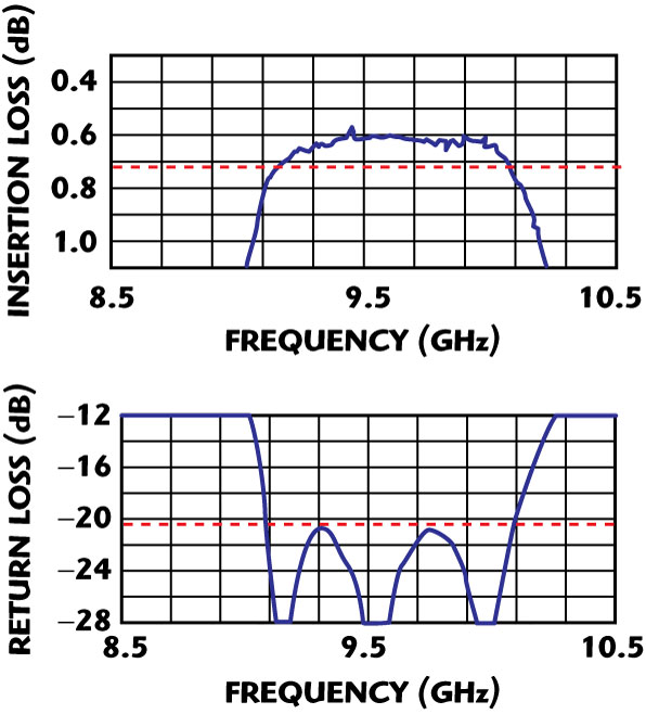
However, a key limitation of any SSRP, when compared to a gas-discharge protector (TR cell), is that the SSRP is a tuned structure, designed to operate in a specific frequency band. This is illustrated in the example of a waveguide SSRP pass-band insertion loss characteristic, shown in Figure 2.
Whereas the operating TR cell would offer an effective short-circuit across a very broad band (from its plasma discharge), the biased-on SSRP will only present a high loss attenuation within the specified frequency band, as shown in Figure 3. Consequently, the required filtering is routinely fitted within the radar system where out-of-band and/or harmonic RF levels may be present, in order to protect the receiver and the receiver protector from out-of-band transients.
Multi-function Receiver Protector

Alongside the limiting or protection functionality of the PIN diode structure of the SSRP, additional functionality may also be integrated within the protector, to provide an integrated multi-function component. The front section of the protector generally contains a high power diode, or doublet of two diodes in parallel, which requires sufficient bias current to enable the stage to handle the incident RF power. The subsequent diode stages are usually less critical in terms of current demand, and generally provide enhanced spike leakage performance as they operate more quickly at intermediate RF power levels.
Consequently, the rear diode stage(s) may be provided with an additional DC bias supply, and driven to provide controlled attenuation for the radar system receive channel. A time-swept attenuation may be provided, enabling precise sensitivity time control (STC) of the radar receiver. In addition, the attenuation stage may be configured to be driven with a simple 1-bit command, to provide (synchronous) blanking attenuation (often termed ‘bang snuff’) within the receiver channel. This shared functionality of limiting and STC attenuation within the rear stages of the RP means that a distinct, separate attenuator block is not required within the receiver chain.
Radar system requirements increasingly demand the suppression of out-of-band signals, both for protection of the receiver and to address radiated EMC requirements of the system itself. An input filter can be incorporated into the SSRP to provide rejection to out-of-band interference.

Where a broader-band response is required of the protector, then some of this filtering may also be integrated within the SSRP itself. An example of this integrated unit is shown in Figure 4. Also, a noise source may be incorporated within the waveguide structure of the SSRP, typically located behind the PIN diode stages. A calibrated excess noise ratio (ENR) signal may then be injected into the receive path (often with blanking/full STC attenuation applied to the limiter, in order to prevent interference from the antenna path), thereby providing a receiver system calibration function.
Built-in-test functionality can be incorporated into the SSRP driver electronics to provide a BIT signal return to the radar receiver controller. For example, window detectors can be added to each of the limiter diode stages, and their outputs AND-ed together, enabling a ‘good’ BIT return provided the limiter diodes are biasing correctly, and remain healthy. Such a BIT scheme is shown in Figure 5.

Another consideration is to maintain system pressurization in an airborne radar system, and prevent moisture/debris ingress into the waveguide of any radar receiver. To this end, a pressure window may be incorporated at the input of the SSRP. A dielectric material panel is fabricated to fit within a frame recess in the input waveguide aperture, and is then bonded into the body of the SSRP.
A pressure window introduces a frequency-dependent additional insertion loss into the SSRP, typically 0.05 dB at X-band (9 to 10 GHz), while offering an aperture seal with hermeticity better than 1 x 10⁻³ mBar ls–1.
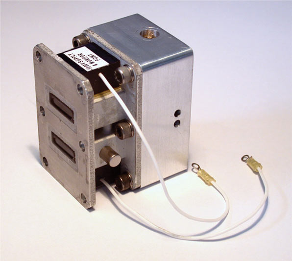
These additional SSRP features and functionality are illustrated in the product example shown in Figure 6, depicting a 500 MHz bandwidth X-band receiver protector, incorporating Ka-band rejection filter, waveguide pressure window, STC attenuation and integrated noise generator. This solid-state passive receiver protector has a waveguide input, SMA coaxial output and a digitally controlled attenuator giving an STC attenuation function from 0 to 60 dB.

It includes four PIN diode stages, with the front stage comprising a PIN doublet. An integrated noise generator is incorporated (14 dB ENR) for system calibration. Its frequency range is 8.7 to 9.2 GHz, with an operating temperature range of –20° to +85°C.
High Power Duplexing/Fault Protection
Some high power radar systems present peak power levels and duty cycles beyond the capability of the solid-state receiver protector. In such applications, whether high power is incident in normal operation or only in a fault condition, then a gas tube element can be incorporated at the input of the receiver protector. Classically, a gas tube element is embodied at the protector input to handle high power levels during normal operation. Incident RF energy first activates the PIN diode stages that provide optimum protection during the RF pulse leading edge, and optimum spike leakage performance.
The increasing E-field level across the waveguide then causes ionization of the gas fill in the tube element, leading to a plasma discharge in the gas tube at a high power threshold level. This discharge presents an effective short-circuit to the incident RF pulse, protecting the receiver across a wide frequency bandwidth from incident high power threats.

The routine use of the gas tube element (within the limiter) for receiver protection or duplexing under normal operation high power conditions is termed a pre-TR configuration. This arrangement is illustrated in Figure 7, showing the pre-TR tube (located in H-plane configuration in this case) within an iris tuning structure across the waveguide input, in front of the solid-state limiter section.
In some applications, the solid-state protector can readily handle all of the normal RF operational power modes, but a very high level fault condition may also be present. In this scenario, the SSRP can be designed with the solid-state limiter optimised for normal RF operation, delivering optimum loss and limiter responsiveness. For the (intermittent) fault scenario, a gas tube can be incorporated at the SSRP input, and used as a gas switch to deal only with any incident fault pulses (synchronous or asynchronous) on an intermittent basis.
With the development of solid-state limiter capabilities to increase peak and mean power handling levels, former TR cell requirements are increasingly being addressed using a solid-state receiver protector. In many cases, the stand-alone SSRP can address the protection requirement, or may be integrated with a gas switch or pre-TR tube in high power fault or high power duplexing applications.
The TR limiter has traditionally been used for duplexer applications with a magnetron-based RF source. Here the limiter typically sees a short pulse, low duty signal, but with high peak power—often many hundreds of kilowatts at S-band or many tens of kilowatts at X-band.
However, the continued use of the TR tube-based TRL has become challenging, owing to the use of radioactive primers to achieve fast response in the gas filling, and the need for a high voltage power supply infrastructure to support the high voltage primer (‘keep-alive’) on the TR tube.
There are three main options for replacing the TR limiter. These include:
• a solid-state diode limiter
• gas tube (pre-TR tube) plus diode limiter
• gas tube (gas switch) plus diode limiter

Utilising a solid-state diode limiter, the operation requirements fall entirely within the capabilities of a modern SSRP. With a gas tube (pre-TR tube) plus diode limiter, the gas tube operates under normal conditions. In this scenario the gas tube is usually referred to as a pre-TR tube. It is used in systems where the pulse conditions (duration, duty) may be more severe at lower power levels, and the recovery specification is not as demanding.
With the gas tube plus diode limiter, the gas tube operates only under fault conditions. The gas tube is often referred to as a gas switch, which is usually fitted when the normal operating conditions require the fast response performance of a diode limiter, plus the high level protection of a gas tube under a high power fault condition. This fault condition is usually present for a short duration. With the protection that this limiter/gas switch configuration offers, the diodes for the limiter can be optimised to meet other operating parameters without the high fault power levels being a concern.
An example of a recent X-band duplexer development entails the replacement of a dual-channel 100 kW TRL unit (shown in Figure 8) with a twin pre-TR limiter (shown in Figure 9). In this application the dual-channel TRL unit is mounted between 3 dB hybrid couplers, so the incident power is split equally between the two channels. Therefore, the power handling requirement per channel, allowing a reasonable margin, is approximately 60 kW peak.
The updated protector design includes a gas tube in each limiter channel in an H-plane orientation. This tube orientation is chosen in order to minimise the arc-loss in the gas tube. Since the device operates continuously at the high power levels, low arc-loss is a requirement for RF and thermal efficiency. The gas switch input section is then followed by a three-stage solid-state limiter.M
Receiver Protector Packaging and Integration
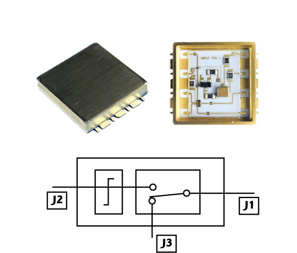
Alongside waveguide units, receiver protectors may also be packaged and configured in strip-line, micro-strip and also as coaxial structures. e2v Technologies has taken the microstrip limiter design approach into surface-mount and ‘drop-in’ packaged devices, which are particularly suited to phased-array radar modules, and developed a surface-mount S-band (E/F band) SPDT reflective switch with limiter protection on its input (J2), as shown in Figure 10.

The limiter section utilises proven diode limiter technology, providing protection at power levels up to +36 dBm CW/ +40 dBm peak, and recovery times better than 200 ns. An integrated SPDT switch circuit within the module offers in excess of 40 dB isolation, with a switching speed better than 2 μs.
The microwave integrated circuit tile is mounted within a surface-mount package, having a 20.5 by 20.5 mm footprint and a height of 3.8 mm. The packaged device is hermetically sealed, and is designed for reflow soldering onto a circuit substrate. The unit operates from a +5 V DC supply, typically drawing a maximum 20 mA. The SPDT switch control is from a –8 V/0 V complementary pair, drawing 1 mA maximum bias current.
Receiver protector topologies can also be realised in a coaxial line structure and an example of a passive S-band coaxial limiter is shown in Figure 11. This low loss S-band coaxial limiter (insertion loss < 0.4 dB, VSWR better than 1.3) is designed for long pulse, high duty operation (100 μs/10 percent duty) at moderate peak power levels. The unit is completely passive, fitting in a compact physical outline with N-type coaxial connectors at input and output.

Alongside receiver protectors, integrated subsystems can facilitate optimum RF system performance, enabling an optimised combination of the receiver protector with other microwave modules and components, into a single integrated package.
For example, Figure 12 shows an integrated Ku-band duplexer/receiver protector/low noise amplifier (LNA) for a man-portable military radar system, which comprises a two-piece integrated microwave package assembly. The integrated unit incorporates a quasi-active receiver protector, circulators, bandpass filter and waveguide probes for BITE signal injection and monitor, with the LNA added at the receiver protector output flange.
From the device schematic, the port 1 connector is a 90° swept male SMA, port 2 is identified, port 3 is the straight SMA female on the LNA and port 4 is the right-angled SMA female with integral 6 dB pad attenuator. The LNA has a waveguide input and SMA coaxial output.
Another example of integration is a Ka-band RF head, comprising a pulse magnetron, four-port circulator, active limiter, LNA mixer pre-amplifier with image rejection, and integrated Gunn oscillator for airborne radar and millimetric imaging applications. The head delivers 1.7 kW peak output power at a nominal 35 GHz, presenting an antenna port match of 1.5 maximum.
The mixer offers a conversion gain of at least 23 dB, down to a nominal IF of 70 MHz. Integration of the receiver protector (in this case an active limiter) within the RF head allows the overall noise figure (from antenna port to the IF output) to be optimised, and is better than 7 dB.
Conclusion
Solid-state receiver protection techniques have been deployed across a wide range of conventional and phased-array radar system architectures, providing low loss protection elements that are capable of withstanding high incident powers from local and remote radar transmitters, along with other EMC threats.
Ongoing development of power-handling capability in the solid-state RP, achieved through diode design, packaging and detector-drive schemes, has enabled SSRPs to replace gas-filled TR cells in the majority of radar systems. Where a high power fault condition persists, and while the solid-state limiter can typically handle all normal operating power levels, then a (non-radioactive) gas switch may also be incorporated in the RP, to operate under fault power levels. Solid-state receiver protection has also been developed in an emerging series of planar circuit configurations, for integration in receiver circuit board architectures to provide low loss protection elements. The integration of further system functionality within the receiver protector assembly supports a further optimisation of the system receiver chain performance and loss, while providing an overall reduction in the radar system mass, size and cost.
References
1. e2v Technologies Ltd., e2v Microwave Product Guide, http://www.e2v.com/ about-us/literature/brochures-and-flyers.cfm.
2. N. Roberts, “A Review of Solid-State Radar Receiver Protection Devices,” Microwave Journal, Vol. 34, No. 2, February 1991, pp. 121–125.
3. R. Cory, Skyworks Solutions Inc., “PIN-limiter Diodes Effectively Protect Receivers,” EDN, 12th December 2004, http:// edn.com/contents/images/486567.pdf.
4. B.M. Coaker, D.M. Dowthwaite and N.E. Priestley, High Power Multi-function Radar Receiver Protection, Proc. European Radar Symposium (EuRAD), Manchester, England, UK, September 2006.
 Brian Coaker joined the English Electric Valve Co. (a GEC subsidiary, later known as EEV, now e2v Technologies), Lincoln, UK, as an apprentice technician engineer. He then read BEng physical electronic engineering at Lancaster University, and went on to read for a total technology PhD at the University of Aston in Birmingham. Having completed his research, he returned to EEV, and was engaged as a senior design engineer, and in 1998 was elected a Chartered Electrical Engineer and Chartered Physicist; he is a member of the Institution of Engineering and Technology (MIET) and a member of the Institute of Physics (MInstP), and is a Whitworth Scholar. He is the author of a number of technical papers in the fields of microwave electronics and electrical breakdown phenomena in vacuum. He is now engaged as marketing manager within the microwave business of e2v Technologies (UK) Ltd., with particular interests in the defence, commercial and maritime radar sectors.