
Testing antenna systems in a realistic deployment environment presents many challenges. While highly-controlled laboratory-based methods remain critical in the design, development and quality control of RF systems, the deployment environment is the ultimate arbiter of performance. In addition, traditional testing approaches can encounter significant constraints when testing large, high-power systems or in installations where there is the potential for complex interference between systems components.
This article discusses the advent of drone-based radio measurement systems. It will explore the challenge of transforming versatile, lightweight drone platforms into high performance radio testing platforms. Their rapid movement and precise 3D positioning can allow open-field and in-situ testing to be utilized where traditional techniques are unavailable and/or cost-prohibitive. A case study exploring the use of practical commercial drone-based measurement technology will be presented, demonstrating the effectiveness of this approach.
The modern environment contains a profusion of radio technologies. Innovation is rapid and the need to be able to evaluate new antenna designs and installations effectively and quickly is pressing. The goal is to accurately characterize the performance of an antenna system that can be expected in a real-world environment.
IDEAL MEASUREMENT ENVIRONMENT
The ideal is to remove all outside influences from the measurement of an antenna system. To perform such measurement requires a shielded environment that is fully impedance-matched with free space, ensuring that all that is measured is the antenna system itself. Once such measurements are obtained, the impact of real-world influences can be superimposed to approximate expected real-world performance.
Open-Field Measurements
An open-field measurement site may provide many of the features required, however proximity to the ground causes coupling, which must either be eliminated or fully accounted for in measurements.1 A clear advantage of this approach is that measurements may be made at a sufficient distance that far-field performance is measured directly. The addition of suitably designed rotation/translation equipment makes scanning possible, however careful design is required to eliminate the artifacts that make such equipment expensive. Exposure to the elements introduces variability that can be challenging to control and account for, except in stable, hot desert environments.
Chamber-Based Measurements
To address the limitations of open-field testing, controlled environments integrating impedance matching (reflection absorbing) materials to approximate open-field performance, along with the device under test (DUT) and measurement antennas enable high-quality predictive measurements.2 Limitations of such environments are size and the associated cost of developing and maintaining these resources. The use of smaller, portable chambers begins to address the issues of cost and maintenance. However, the size limit creates additional constraints, such as the need to operate in the near-field, derive the approximate far-field performance and the limited size of the DUT.
Freely-Positioned Measurement Devices
Open-field measurement is an attractive approach. However, a key problem arises when measuring the radiated field if the required measurement scope exceeds the parameters of any purpose-designed measurement range. If it were possible to measure the radiated field at any position, in any orientation and at any distance around an antenna, then a new space of possible measurement approaches would become available.
In-Situ Measurements
The ultimate arbiter of performance is how antennas perform in the application environment, whether they are mounted on a tower, a ship, an airframe or any other application where installation location, installation faults and other interfering equipment will contribute to system performance. These environments are also not ideal, with factors like obstructions, reflections and weather influencing the system behavior.3 These influences are approximated in system design, but real-world surprises still abound, leading to unexpectedly poor performance. The diagnosis of and solution for these issues requires in-situ measurement. Current techniques for this are limited to utilizing ground-based antennas up to approximately 10 meters above the ground or commercial helicopters with their attendant complexity and cost. Standards for such measurements have been developed.4
DRONE-BASED MEASUREMENTS
The remainder of this article addresses the use of modern drone technology to both provide for an expansion of the open-field testing approach and to offer, for the first time, a means to provide high-quality in-situ diagnostic measurements during normal system operation across a wide variety of antenna system applications. The aim is to provide this test capability rapidly and at a low cost.
Enabling Technologies
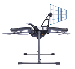
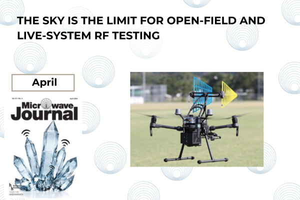
Figure 1 Integrated drone-based measurement platform.
An ideal, freely-positioned measurement device can be approximated using modern rotor-based drone technology and low-cost, high performance, headless software-controlled radio receivers. An example of this technology is shown in Figure 1.
Drone Platforms
Early drone platforms experimented with several configurations. Typical attributes of modern drone platforms that can be used for this type of operation are:5-8
- A quadcopter configuration that is typically 85 to 100 cm in diameter
- 1.5 kg payload capacity
- 20 to 30 W available payload power supply
- 30-minute flight time
- Direct communication from the flight controller to the payload is available
- Automatic waypoint generation and flight control.
Headless Software-Controlled Radio Platforms
Disruption to traditional radio measurement has arisen in the form of high performance headless programmable radio platforms or software-controlled receivers (SCRs). Utilizing modern design techniques, these devices boast performance comparable to high-end integrated measurement equipment. However, they lack a purpose-built user interface because they require the use of a host computer to provide an application solution like traditional spectrum analysis. When first introduced, these platforms had significant sampling speed and frequency range performance constraints, but these limitations have been aggressively addressed in subsequent generations. Current devices offer full traceable calibration and can cover frequency ranges from 9 kHz to 40 GHz, exploiting high speed communications such as USB 3 and gigabit Ethernet to realize performance that directly competes with traditional integrated measurement platforms. A representative sample of offerings is presented in the references.9-11 Typically, these SCR platforms have a dynamic range better than 90 dB, noise figure better than -154 dBm/Hz, low phase noise and excellent image rejection.9
Drone Compatibility
A limitation of drone platforms is the available payload weight and power supply performance. Any measurement mission will require sufficient autonomy to perform the required measurement sweep in a single flight. Fortunately, recent innovations have delivered high performance, low-weight, low-power SCR packages that are compatible with current drone technology.9,11
Compute Platforms
Single-board computers based on Intel and ARM architectures are widely available. They are both lightweight and have low power demands, providing sufficient support for suitable SCRs while not exceeding feasible drone payload constraints. Single-board compute platforms can also integrate significant processing through multi-core CPUs and inexpensive low-power, high speed storage using solid-state drive technology such as contemporary M.2-type units with high capacity and excellent write performance.
SOFTWARE
Leveraging these component technologies to provide a complete measurement solution requires the addition of various software components that are briefly outlined below.
Data Capture
The APIs for SCRs are diverse; standards such as VITA49.112 do not enjoy significant support. Despite this apparent limitation, the task of programming data capture, even for diverse device types, is straightforward, as API design has evolved toward ease of use. Most SCR APIs5,6 provide for both swept spectrum capture and time-domain (IQ) capture with flexible parameter programming utilizing modern host languages like C++ and Python. For both measurement modes, the state-of-the-art capture rates achieved by feasible drone payloads can be extremely high; on the order of 20 GHz/sec scan rate for spectral capture at 10 kHz RBW and up to 40 MHz for continuous IQ capture. The expectation is that these figures will only improve with time.9-11 These levels of performance imply captured data rates on the order of 100 MB/sec. A single 30-minute flight could theoretically generate on the order of 200 GB of data.
Data Fusion
The SCR and compute platform will provide IQ or swept-spectra radio data correlated with time. The flight control system utilizes referenced GPS and it provides highly accurate position data with centimeter resolution correlated with time.5-8 Combining these data streams provides the calibrated radio measurement data, accurately positioned in space and time, that are of critical importance.
The required spatial resolution is a constraint that must be accounted for in such a fusion of data. Consideration must be taken for the capture rate for the required data, versus the programmed spatial tracking speed of the drone platform. Once a measurement pattern is determined, software can provide the constraints required for flight path planning. In practice, this does not significantly constrain drone tracking speed.
In-Flight Processing
While it is feasible to capture all the data from a flight, a more sophisticated measurement approach will typically be utilized to maximize efficiency. Where a complex installation is being measured, there may be multiple disjointed bands of interest. A single “tuning” may not capture all the required data and if this occurs, dynamic switching between measurement bands may be required. Multiple antennas may be required to capture all the data and this requires more sophisticated sequencing.