
RF connectors fulfill a critical role in virtually all radio and RF test and measurement products and components. They provide the gateway to, from and within the entire signal chain and can either be a key enabler or the primary issue for any design. Proper selection of an RF connector from the vast variety of geometries available is important and can be daunting. However, methodical consideration of key selection factors can enable getting to a functional choice. As each selection factor is considered, the choices should quickly narrow to the best workable solution or at least a much smaller list of choices.
The selection factors we’ll examine are:
- Frequency Coverage
- Transition Performance
- Attachment Method (Soldering or Solderless)
- Spacing Requirements
- Connection Retention Type
- Mating Cables
- Repeatability and Mating Cycles
- Serviceability
- Calibration Requirements

Figure 1 Coaxial connector cross-section.
These are listed in the generally recommended order for consideration to efficiently narrow the choices. If you have specific design constraints that align closely with one of these factors, such as tight spacing for several connections, then you may want to adjust the order. It is recommended that you consider all the factors before making a final decision to build consistency in the process. It might be tempting to quickly dismiss the factors you think do not apply, but going through the complete process can help avoid major unseen issues down the road.
Cost was not listed as a separate factor since it is pervasive throughout all the factors. While considering each factor, the balance between cost and fulfillment of requirements will need to be weighed. As a result, it will be important to clearly define the minimum acceptable levels required for each factor to avoid paying for something you do not need.
FREQUENCY COVERAGE
The physical dimensions of an RF connector’s coaxial structure will define the frequency it can transmit. The cutoff frequency of an RF coaxial structure specifies the highest frequency at which the desired transverse electromagnetic (TEM) mode can freely transmit, while unwanted higher-order modes will dissipate quickly. Fundamentally, smaller coaxial structures will support higher possible frequency transmission.
To provide a mathematical example of this, the cutoff frequency for a coaxial connector, as shown in Figure 1, with an outer conductor inner diameter of Do and an inner conductor outer diameter of Do using an air dielectric can be approximated in Equation 1:
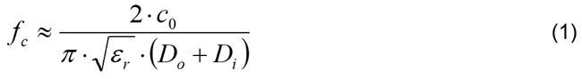
Where:
c0 is the speed of light
εr is the relative dielectric constant in air.

Table 1 Cutoff and specification frequencies for common connector types.
As one can see by the presence of the coaxial diameters in the denominator, to increase the cutoff frequency limitation the total diameter of the coaxial structure must shrink.
This is reflected in the frequency ratings of the many standardized coaxial RF connector options, with the smallest connectors supporting the highest frequencies. Most connector standards set the frequency rating of the connector a little bit below the theoretical cutoff frequency of the geometry. This is shown in Table 1.
The options shown in Table 1 are only the most common threaded RF connector standards. There is a plethora of additional coaxial RF connectors on the market, some standardized and some proprietary, that cover overlapping regions of the frequency spectrum. Figure 2 shows a partial collection of connector options, their dielectric type and their typical frequency ratings. In some cases, certain manufacturers may offer extended frequency ratings for a given connector. This is usually achieved through slight modifications to the coaxial geometry or tighter tolerance control than what may be specified by the standards.

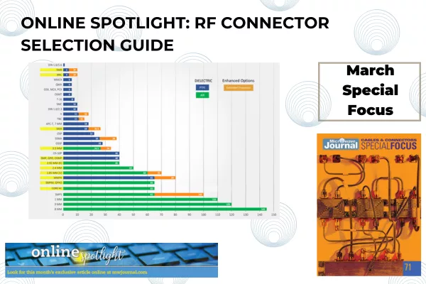
Figure 2 Dielectric type and frequency rating for common connector types.
TRANSITION PERFORMANCE
The frequency coverage described provides only an upper boundary for what frequency a connector type can handle. The actual usable frequency can be much lower based on the transitions that the RF signal must traverse as it travels through the connector from one end to the other. There may be interior construction details, changes in material type or changes in the transmission geometry that dictate the real performance of the connector. This is particularly important when the connector is used to transition the signal from a coaxial cable to a flat circuit or PCB transmission line.
The RF signal transitions result in a reflected signal that is measured as return loss or VSWR. The amount of reflection is directly related to how abrupt or severe the mismatches are. The transition from a nice coaxial structure to a planar transmission line is particularly challenging to accomplish without introducing a sizable return loss.
As illustrated in Figure 3, return loss (S11) and VSWR both relate the ratio of how much signal is reflected to how much is incident at the measurement point. These reflections will accumulate to some degree along the signal chain, but the overall value will tend to be dominated by the largest reflections in the chain.

Figure 3 Definition of terms.
As a general rule, if the return loss directly associated with the connector transition is greater than 20 dB (VSWR = 1.22), then the impact on the transmission can be neglected. The specific use case and other elements in the signal chain may either dictate a need for better return loss, or tolerance for lower return loss.
Return loss is also frequency-dependent and generally degrades as the frequency increases. If the mismatch in the connector transition is large, the degradation with frequency can be very dramatic as illustrated by this return loss plot for a common straddle mount SMA connector shown in Figure 4.
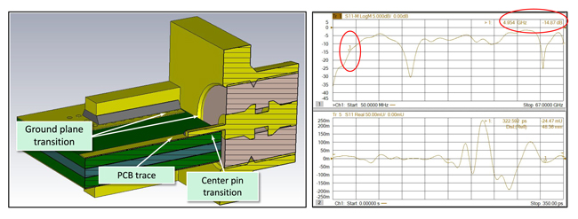
Figure 4 Return loss for an SMA connector.
The SMA connector example of Figure 4 would generally be considered an 18 GHz connector standard, but the usable frequency range is limited to only about 4 GHz due to the physical transition mismatch limitations of the connector design. If your connector will be the bridge across this sort of transition, then it is important to understand that the usable frequency range will be highly dependent on managing and minimizing the mismatch the signal encounters as it moves through the transition. Some connector choices have geometries that help in this area, but it is recommended to use simulation tools to ensure that the return loss will be acceptable for the specific materials, geometries and requirements. If you cannot perform this simulation, many of the leading RF connector suppliers offer simulation as a service. Additionally, if your application is particularly dependent on achieving very low return loss, then building a connector test board to verify the transition performance is recommended.