
6G aims to be the first generation of wireless technology to improve the quality of human life by bridging the physical, digital and human worlds. Accomplishing this will mean adding artificial intelligence to networks to make them more efficient and building high-fidelity digital twins. It will also require building upon network architectures like non-terrestrial networks and highly virtualized disaggregated networks that began in 5G and expanding spectrum use.
For 6G to meet these goals, the spectrum allotted for wireless communications must be used more efficiently and new spectrum must be studied. Without expanding into new spectrum bands, it will be impossible to meet the high data throughput and volume needs of applications like immersive telepresence, virtual reality and extended reality. There are three fundamental approaches to achieving high data throughput.
One approach involves using higher-order modulation schemes such as 64-QAM to increase the number of bits transmitted for each symbol. Given a fixed and finite spectrum bandwidth, increasing the modulation order from QPSK, which transmits two bits for each symbol to 64-QAM, which transmits six bits for each symbol would increase the data throughput by a factor of three if channel conditions and radio performance allow. A 1 GHz QPSK symbol rate would result in a 2 Gbps theoretical raw calculated data throughput without forward error correction (FEC) coding rate redundancy. However, increasing the modulation order to 64-QAM would result in a 6 Gbps data throughput, while using the same spectrum-occupied bandwidth.
The second approach uses more spectrum bandwidth and increases data throughput by using a higher symbol rate. For example, with the 1 GHz symbol rate, the occupied channel bandwidth is approximately 1.22 GHz, assuming a 0.22 root-raised cosine filter alpha or excess bandwidth. Increasing the symbol rate by a factor of 10 to 10 GHz would increase the QPSK data throughput to 20 Gbps but would use a much wider swath of spectrum, approximately 12.2 GHz. However, increasing the modulation order as the symbol rates and modulation bandwidths increase becomes more challenging due to reduced signal-to-noise (SNR) ratio, greater amplitude and phase impairments and other technical challenges.
A third approach transmits multiple and independent streams of data using multiple antenna techniques such as MIMO. MIMO exploits radio channel complexity and simultaneously transmits and receives multiple and independent data streams for higher data throughput. The data throughput can be increased using 2 × 2 MIMO for the 1 GHz QPSK symbol rate by transmitting two streams of data simultaneously. The actual increase, however, would depend on the channel conditions and system overhead so this will increase the data throughput but not necessarily double it.
The second approach of using a large swath of spectrum bandwidth was previously explored and published in a Microwave Journal article1 demonstrating a quasioptic over-the-air (OTA) transmission at 285 GHz with 30 GHz bandwidth. 30 GHz occupied bandwidth corresponds to a bandwidth where data throughput can exceed 100 Gbps for a single stream of data.2 The data throughput for the quasioptic OTA transmission was calculated to be 97 Gbps without FEC coding rate redundancy using an 802.15.3d frame structure.
This article will explore and discuss the third approach of using sub-terahertz (THz) MIMO to exceed 100 Gbps. A sub-THz MIMO testbed for 6G research demonstrates simultaneous 2 × 2 MIMO at D-Band (142 GHz) and H/J-Band (285 GHz). These two sub-THz frequency bands were selected to show feasibility in two key frequency bands of interest for 6G high data throughput. The total theoretical data throughput across all four channels is calculated to be approximately 126 Gbps for custom orthogonal frequency-division multiplexing (OFDM) waveforms with a 16-QAM modulation order, transmitting OTA and using a 12.5 GHz occupied bandwidth for each signal.
SUB-THZ MIMO TESTBED FOR 6G RESEARCH
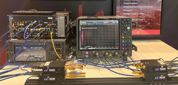
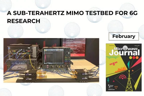
Figure 1 Simultaneous 2 x 2 sub-THz MIMO OTA transmission at D-Band and H/J-Band.
Figure 1 shows a sub-THz MIMO testbed that can be used for 6G research. An M8199A 128 GSa/s four-channel AWG generates wide bandwidth modulated IF signals. The M8199A AWG has an analog 3 dB bandwidth of 65 GHz. Channels 1 and 2 of the AWG generate wide bandwidth modulated IF signals centered at 11 GHz that are input into the Virginia Diodes Inc. (VDI) compact WR6.5 dual up-converter inputs on the top left of the four VDI converters shown in Figure 1. Channels 3 and 4 of the AWG generate wide bandwidth modulated IF signals centered at 16 GHz. These signals are input into the VDI compact WR3.4 dual up-converter inputs on the bottom left of the four VDI converters.
An M9384B VXG dual-channel microwave signal generator generates two different local oscillator (LO) signals for the VDI compact dual up-converters and dual down-converters. Channel 1 of the VXG generates a 25.5 GHz CW LO signal, which is power split with an external power splitter to provide LO signals for the WR6.5 dual up-converter on the top left and the dual down-converter on the top right of the four VDI converters. Channel 2 of the VXG generates a 22.4166 GHz CW LO signal which is power split with an external power splitter to provide the LO signals for the WR3.4 dual up-converter on the bottom left and dual down-converter on the bottom right of the four VDI converters shown in Figure 1. The LO signals are internally multiplied within the VDI WR.6.5 dual converters by a factor of six to yield a high-side LO signal of 153 GHz and a factor of 12 within the WR3.4 dual converters to yield a low-side LO signal of 269 GHz.
The two 11 GHz wide bandwidth modulated IF signals are up-converted to 142 GHz by the WR6.5 dual up-converter on the top left. The two D-Band output waveguide ports have orthogonal polarization, with one output horizontally polarized and the other output vertically polarized. VDI waveguide bandpass filters are used to filter out the undesired upper sideband signals and LO feedthrough signals and pass the desired lower sideband signals of 142 GHz (153 GHz LO - 11 GHz IF = 142 GHz). The 142 GHz signals are amplified with a VDI WR6.5 waveguide amplifier and transmitted OTA with two WR6.5 rectangular horn antennas. On the receive side, the 142 GHz signals from the two receive WR6.5 rectangular horn antennas are down-converted to two 11 GHz IF signals by the WR6.5 dual down-converter shown on the top right.
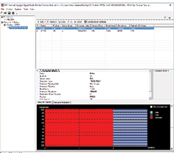
Figure 2 N7608C custom OFDM MIMO signals.
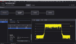
Figure 3 N7618APPC PathWave Signal Generation Advanced Waveform Utility display.
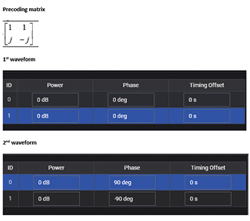
Figure 4 Applying precoding in N7618APPC PathWave Signal Generation Advanced Waveform Utility.
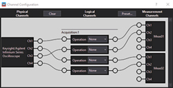
Figure 5 VSA channel configuration.
The two 16 GHz wide bandwidth modulated IF signals are up-converted to 285 GHz with the WR3.4 dual up-converter shown on the bottom left of Figure 1. The two H/J-Band outputs have orthogonal polarization, with one output horizontally polarized and the other output vertically polarized. VDI waveguide highpass filters are used to filter out the undesired lower sideband signals and LO feedthrough signals and pass the desired upper sideband signals (269 GHz LO + 16 GHz IF = 285 GHz). A higher IF frequency of 16 GHz is used, instead of the 11 GHz used for 142 GHz, to provide more rejection of the LO feedthrough and undesired lower sideband signal (269 GHz LO – 16 GHz IF = 253 GHz) with the highpass filter. The 285 GHz signals are amplified with a VDI WR3.4 waveguide amplifier and transmitted OTA with two WR3.4 diagonal horn antennas. On the receive side, the 285 GHz signals from the two receive WR3.4 diagonal horn antennas are down-converted to two 16 GHz IF signals with the WR3.4 dual down-converter shown in the bottom right.
The waveguide slot orientations for the WR6.5 and WR3.4 dual up-converters and dual down-converters are aligned to provide the correct horizontal or vertical polarization when the dual up-converter and down-converter waveguide ports are facing each other, as they are in Figure 1. This can be seen in the width, height and orientation of the four WR6.5 rectangular horn antennas facing each other since the width and height dimensions are different. This is more difficult to observe with the WR3.4 diagonal horn antennas since the width and height dimensions are the same.
The two 11 GHz wide bandwidth modulated IF signals from the WR6.5 dual down-converter and the two 16 GHz wide bandwidth modulated IF signals from the WR3.4 dual down-converter are input into channels 1 and 3 and channels 2 and 4 of the 33 GHz UXR four-channel real-time oscilloscope to digitize and analyze the MIMO wide bandwidth IF signals. The 33 GHz UXR has a 128 GSa/s sample rate on all four channels.
MIMO TESTBED SIGNAL GENERATION SOFTWARE
Keysight’s N7068C Signal Studio Pro for Custom Modulation and N7618APPC PathWave Signal Generation Advanced Waveform Utility (PWSG AWU) are used to generate and download the custom OFDM waveforms to the M8199A AWG. The symbol index, subcarrier index, resource modulation order (QPSK, 16-QAM) and payload PN sequences can be specified for data and DMRS resource blocks using N7068C Signal Studio Pro for Custom Modulation shown in Figure 2. The system sample frequency is set to 16 GHz and over-sampled by two to 32 GHz before exporting the .csv files.
PWSG AWU in Figure 3 imports the .csv files and up-samples the waveforms to download them to the M8199A AWG using IF frequencies of 11 GHz for channels 1 and 2 and 16 GHz for channels 3 and 4.
The waveforms downloaded to the M8199A for the MIMO measurements are ideal. However, wideband channel flatness performance may not meet the test requirements when waveforms are played from real hardware. PWSG AWU provides a pre-correction wizard to automate correction filter file generation using PathWave 89600 vector signal analysis (VSA) software, which can be useful for very wide bandwidth signals at sub-THz frequencies. This pre-correction occurs by digitizing the waveforms with the UXR and then applying the reverse of the channel response from the VSA to the waveform. Users can download the waveform applied with the correction filter file to M8199A or export it to a new waveform file.
Precoding could also have been applied in the PWSG AWU software to help maximize data throughput for non-LOS scenarios. Consider the precoding matrix shown in Figure 4 for example. The two pre-coded waveforms can be generated with the phase setup shown after the two MIMO waveforms are imported as two carriers, assuming that different payload bits are used for the two waveform setups. However, the custom OFDM waveforms for this demonstration were directly mapped to the antennas and not pre-coded. Waveguide horizontal and vertical polarization were used to separate the MIMO streams of data, which was sufficient for this LOS application.
MIMO TESTBED SIGNAL ANALYSIS SOFTWARE
PathWave 89600 VSA software is used to analyze and demodulate the four digitized IF signals from the UXR oscilloscope. A custom channel configuration is set up in the VSA to map the UXR input channels to logical channels and VSA measurement channels shown in Figure 5. UXR physical channels 1 and 3 correspond to the WR6.5 dual down-converter IF outputs. These are mapped to VSA Meas01 channels 1 and 2. UXR physical channels 2 and 4 correspond to the WR3.4 dual down-converter IF outputs. These are mapped to VSA Meas02 channels 1 and 2. Meas01 is the D-Band MIMO demodulation measurement and Meas02 is the H/J-Band MIMO demodulation measurement. The VSA measurement acquisition mode is set to acquire Meas01 and Meas02 simultaneously and not sequenced. VSA multi-measurement is set up to process and display multiple MIMO measurements (Meas01 and Meas02) concurrently.
For the VSA demodulation setup, the 89600 VSA setup files are exported from N7068C Signal Studio Pro for Custom Modulation with the OFDM setup parameters specified previously for signal generation. These parameters include, for example, symbol index, subcarrier index, resource modulation order and payload PN sequences for DMRS resource blocks. Equalizer and tracking parameters are set in the VSA software for the physical testbed measurement, for example, least squares equalizer averaging mode.
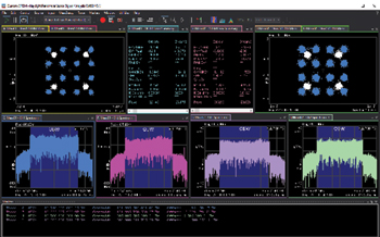
Figure 6 Display of VSA demodulation of custom OFDM MIMO signals.
VSA demodulation of the simultaneous 2 × 2 custom OFDM MIMO signals at 142 GHz and 285 GHz is shown in Figure 6. Two PSG signal generators with option UNY were used for the two LO signals, instead of the VXG dual-channel signal generator shown in Figure 1. In addition, a four-channel 110 GHz UXR was used instead of the 33 GHz UXR. Pre-corrections were applied with PWSG AWU for the waveguide-to-waveguide connected signal path including the AWG, VDI dual up-converters, VDI filters, VDI dual down-converters and UXR. The VDI amplifiers and horn antennas were not included in the pre-corrections.
The 142 GHz MIMO demodulation results are shown on the left of Figure 6 and the 285 GHz MIMO demodulation results are shown on the right of Figure 6. The 16-QAM constellation and OFDM error summary tables are shown on the top row of the display in Figure 6 for 142 GHz (left) and 285 GHz (right). The four spectrum measurements are shown in the middle row for 142 GHz channels 1 and 2 (left two spectrums) and 285 GHz channels 1 and 2 (right two spectrums). The measured occupied bandwidths of each of the four spectrum measurements are shown at the bottom of the VSA display in Figure 6. The occupied bandwidths are measured to be approximately 12.5 GHz for each of the four sub-THz signals.
For simultaneous 2 × 2 custom OFDM MIMO signals at 142 GHz and 285 GHz, the total theoretical data throughput across all four channels is calculated to be approximately 126 Gbps for a 16-QAM modulation order. Although a specific MIMO configuration is shown in this example for demonstration purposes, the testbed is flexible for emerging sub-THz MIMO research. The flexibility of software combined with flexible multichannel instruments in this testbed can be used to research and explore candidate 6G MIMO waveforms and to evaluate their performance for various MIMO configurations at different frequencies and bandwidths.
SUMMARY
Using sub-THz MIMO to transmit multiple independent streams of data using multiple antenna techniques is one approach for achieving 100 Gbps data throughput for 6G. Alternatively, or additionally, using extreme SISO transmission bandwidths, such as 30 GHz bandwidth at 285 GHz, is another approach for achieving 100 Gbps. The sub-THz MIMO testbed for 6G research discussed in this article demonstrates an example of using sub-THz MIMO to exceed 100 Gbps.
Simultaneous 2 × 2 MIMO at D-Band (142 GHz) and H/J-Band (285 GHz) is demonstrated using VDI compact WR6.5 and WR3.4 dual up-converters and dual down-converters with horizontal and vertical polarization. The total theoretical data throughput across all four channels is calculated to be approximately 126 Gbps for a 16-QAM modulation order. These data rates were obtained while transmitting OTA and using a 12.5 GHz occupied bandwidth for each signal.
Custom OFDM MIMO waveforms were generated and analyzed using flexible signal generation and analysis software for candidate 6G waveform research. Precoding could have also been applied using signal generation software. Combining flexible signal generation and analysis software with flexible multichannel high performance AWGs, multichannel microwave sources, multichannel high performance oscilloscopes and VDI compact dual up-converters and down-converters provides a high performance and flexible testbed for emerging sub-THz 6G MIMO research.
References
- “A Quasioptic OTA Transmission at 285 GHz with 30 GHz Bandwidth,” Keysight, 2022, Web: https://www.microwavejournal.com/articles/39772-a-quasioptic-ota-transmission-at-285-ghz-with-30-ghz-bandwidth.
- “6G: Going Beyond 100 Gbps 1o 1 Tbps,” Keysight, 2021, Web: https://www.keysight.com/zz/en/assets/7121-1152/white-papers/6G-Going-Beyond-100-Gbps-to-1-Tbps.pdf.