
.webp?t=1679596290)
RF mezzanine board-to-board (BTB) connectors have been used extensively to allow for RF signal connections between the RF power amplifier printed circuit board (PCB) and the radio transceiver (PCB) within radio units (RUs) and remote radio units (RRUs) since the transition from UMTS to LTE technologies for wireless mobile radio access networks (RAN). These radio systems were low order MIMO systems ranging from 1T2R, 2T2R, 4T4R and 8T8R architectures. The quantity for these RF BTB connectors was one set for each RF channel, consisting of two male PCB connectors (either through hole or surface-mount) and one female-female bullet to connect the transmit (Tx) and receive (Rx) paths from the radio transceiver PCB to the power amplifier PCB and one set to connect the power amplifier PCB to the RF channel filters.
An Ericsson RRUS11 (code named Platform 4) 2T2R LTE RRU, shown in Figure 1, is used as an example of this type of radio system architecture shipping in the 2010 to 2013 timeframe with ten sets of RF micro coaxial connector (MCX) BTB connectors between the radio TxRx PCB and the RF power amplifier PCB with quick lock SMA (QMA) cable connectors between the RF power amplifier PCB and the RF duplexer filters.
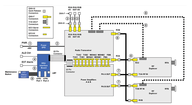
Figure 1 Ericsson RRUS11 example (Source: EJL Wireless Research).
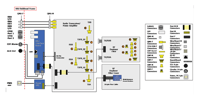
Figure 2 Ericsson RRUS12 example (Source: EJL Wireless Research).

Figure 3 MWC Barcelona 2015 ZTE 64T64R pre-5G mMIMO radio/antenna system (Source: EJL Wireless Research).
The Ericsson RRUS12 (code named Platform 5) 2T2R LTE RRU, shown in Figure 2, is an example of the next generation radio system architecture shipping in the 2012 to 2015 timeframe. This radio system architecture had eight sets of subminiature push-on (SMP) BTB connectors and only one PCB (radio TxRx/RF power amplifiers) and the RF duplexer filter and replaced the QMA cable connectors with blind mate catcher’s mitt SMP BTB connectors to reduce the manufacturing complexity compared with RF cable assemblies.
IMPACT OF MASSIVE MIMO RADIO SYSTEMS
The introduction of production 64T64R massive MIMO (mMIMO) radio systems (see Figure 3), coupled with pre-5G mMIMO systems by the Chinese OEMs (Datang Telecom, Fiberhome Technologies, Huawei Technologies and ZTE Corporation) for China Mobile’s TDD-LTE 4.5G mobile network in the 2015 to 2016 timeframe created a high volume requirement for high performance low-cost 5 to 20 W RF BTB connectors for first generation system architectures. The integration of the antenna array within the radio system architecture increased the requirement for the quantity of BTB connector “sets” for a 64T64R system from the radio TxRx/RF power amplifier PCB to the RF filter distribution PCBs to also include the RF signal paths between the RF filters to the mMIMO antenna array PCBs.
An example, shown in Figure 4, of an early first-/second-generation 64T64R radio system architecture uses 66 sets of MMBX through hole male catcher’s mitt and female-female bullets to connect the radio TxRx/power amplifier PCB to the RF filter subsystem. Each dual-channel RF filter has two MMBX male catcher’s mitt connectors and two MMBX female connectors for a total of 128 RF connectors for each 32T antenna array. In this architecture example, a total of 326 RF connectors are needed to complete the system. The length of the barrel/bullet connectors depends upon the clearance needed between the radio TxRx RF shield and the RF filter subsystem and/or the RF filter subsystem to the antenna/combiner PCB.
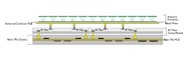
Figure 4 Sub-system PCB stack for 64T massive MIMO radio antenna system (Source: EJL Wireless Research).
POGO PINS FOR RF BTB CONNECTORS
Pogo pins have been used extensively as probe contacts for semiconductor test equipment and can handle high levels of current, up to 30 A, but typically have been as a signal/electrical contact source where the entire body is metal as shown in the examples in Figure 5 with an inner spring mechanism.
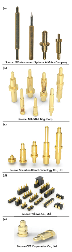
Figure 5 Various examples of pogo pins from different manufacturers.
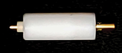
Figure 6 First-generation pogo pin design for Huawei AAU (Source: EJL Wireless Research).
Before its export ban in May 2019, Huawei Technologies had already replaced the costly MMBX/SMP RF BTB connectors with low-cost pogo pins for all of its RF coaxial connectors for all of its 5G mMIMO radio antenna system platforms, substantially decreasing the global TAM for these types of RF connectors although the company continues to use RF coaxial connectors for its high-power 5G RRUs. The first generation pogo pins used are shown in Figure 6 while the improved second-generation design is shown in Figure 7.
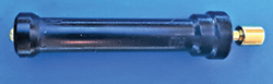
Figure 7 Second-generation pogo pin design for Huawei AAU (Source: EJL Wireless Research).
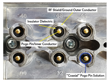
Figure 8 Second-generation coaxial pogo pin BTB example for mMIMO radio systems (Source: EJL Wireless Research).
What is different about the pogo pins used for RF signal paths as shown in Figures 6 and 7, is that the pogo pin itself acts as the center conductor for a coaxial connector with the insulative housing surrounding the pogo pin (see Figure 8). The pogo pin and insulative jacket is then inserted into an RF shield system which acts as the outer conductor or ground plane for the coaxial pogo pin system.