
A more accessible and universal approach is to use surface, through-hole or edge-mount coaxial connectors that are attached to the landing pads with solder. If bonded properly, this method can provide a rugged connection that can be both reliable and compact. This method does require some effort to ensure alignment, but some connector types can be assembled automatically by pick and place technology. The main issue with this approach is the limitation of the tolerances of the solder bonds between the center and ground pins of the coaxial connectors and the landing pads. At 100 GHz, the free space wavelength is about 3 mm. A common rule of thumb is that geometric features that are on the order of one-tenth or even one-twentieth of a wavelength are significant. This means that achieving feature sizes for the solder connections that are less than 300 μm and even 150 μm is required for high precision and repeatable interconnect applications. This is not readily done by hand without the tools and expertise of a skilled technician, but it is within the capability of machine assembly.
A solution to address the repeatability problem is to use pre-manufactured or custom solder test leads. However, the frequency limitations of this solution make it more suitable for use with oscilloscopes for probing time-domain signals to several GHz. These are used in place of hook or hand-probed interconnects. These connection types are only capable of reaching a maximum specified frequency range of 20 GHz. They are also costly to use and are often limited to single-use or several uses at most. Ultimately, these types of connectors are not suited to upper mmWave applications.
Another approach is to avoid attaching the test leads to the landing pads and instead press the precision contacts of transmission lines to the landing pads. A probe station can test these board-level test points and transmission lines while only minimally impacting the test board. Some precision probes reach 500 GHz of bandwidth using ground-signal-ground style probe tips with waveguide interconnect. Alternatively, precision probes can reach up to 145 GHz with a coaxial interconnect. Some probes have multiple signal lines on a single probe head, which could help test multiple high speed differential lines. However, using precision probes requires a probe station, which is typically a capital expense item and requires an experienced technician to operate.
COMPRESSION CONNECTOR BENEFITS
Another commonly available option for high precision mmWave interconnects is threaded, coaxial compression connectors. This type of connector is becoming more popular because of its ease of use, reusability, repeatability and performance. Compression connectors are much like soldered coaxial connectors, with the exception that the center conductor and ground connections are made through precision-designed compression contact surfaces, similar to a probe station and they do not require soldering for attachment. Instead, mounting screws are typically used to provide the fixturing and alignment.
Since soldering and through holes are not required, surface mount compression connectors can be used on traces anywhere on the board surface and not just the edge. End-launch compression connectors require a precision milled surface at the edge of the board that is precisely positioned with respect to a surface planar transmission line. This does not fit all testing applications, so a surface mount compression connector that can be attached to mounting holes anywhere on the surface prevents the need to route planar transmission lines to the edge of a board.
COMMON METHODS OF COMPRESSION CONNECTOR ALIGNMENT
mmWave compression connectors are compact in size. The overall footprint for 2.92 mm board connectors that will provide 40 GHz maximum mode-free frequency operation is typically around 10 x 6 mm with about 7 mm pitch between mounting screws. For 1.35 mm board connectors, these dimensions shrink to about 10 x 4 mm with a similar pitch. However, the center contact diameter for the 2.92 mm connector is around 508 μm and the center contact for the 1.35 mm connector is half of that, at 254 μm. The trace widths of the landing pads for these connectors are roughly the same dimensions as the center pin diameters. That means that the tolerances to achieve an optimal interconnect with the 1.35 mm connector is roughly half of that of a 2.92 mm connector, leaving little margin for error.
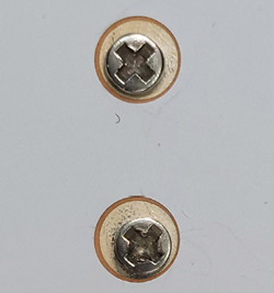
Figure 1 Potential tolerance issues arising from screw or pin alignment with machined holes in a PCB.
Methods are needed to ensure alignment with these connectors so that the connections are precise and repeatable. The most common method relies on the screws used to fixture the compression connector to the RF board. Another common method uses alignment pins that are inserted through a feature on the compression connector body and the PCB.
There are a few challenges with these approaches. The PCB manufacturing process is done in several stages with large format boards that undergo etching, solder mask, silk-screening and milling in different machines. These boards are likely handled by different operators in a high-paced manufacturing environment, which means indexing the large format PCB at every stage for each job, often using mechanical and visual indicators.
This fixturing can be manufactured to reasonable tolerances, but it varies from board to board and the run-out of a board can be inconsistent between runs. The machining tolerances of a board can also vary depending on the tooling type, tool wear, operator skill and machine calibration. This leads to a tolerance stack-up between the etching and machining operations that can easily amount to hundreds of micrometers. Since this tolerance stack-up is the same order of magnitude as the contact area and trace widths used in upper mmWave interconnects, it can easily lead to misalignment issues based on screw or pin misalignment with the machined features of a PCB. This analysis does not include potential tolerance issues associated with manufacturing the screw or alignment pin along with the connector housing mounting holes, which would also contribute to the overall alignment accuracy of these methods. Some examples of these tolerance issues are shown in Figure 1.
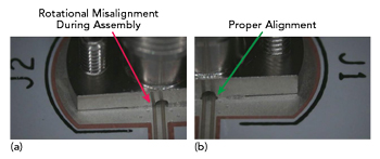
Figure 2 Rotational misalignment (a) and proper alignment (b) of a compression connector on a PCB.
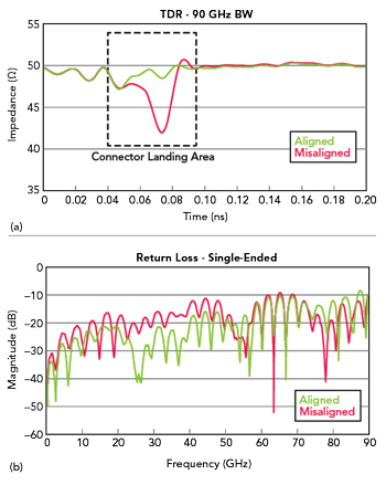
Figure 3 TDR measurement of an aligned and misaligned 1.35 mm compression connector (a). Return loss of aligned and misaligned connectors at the landing area (b).
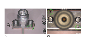
Figure 4 Side view of visual alignment grooves on a 1.35 mm threaded compression-mount coaxial connector (a). Top view of visual alignment grooves on a 1.35 mm threaded compression-mount coaxial connector (b).
Alignment issues may also allow enough “play” between the two screws to permit undesirable rotation around the axis of the coaxial connector as shown in Figure 2. The dimensions between the signal trace and the ground of the connector housing are critical for the electrical performance of the connection interface, so this type of misalignment can cause transmission line performance degradation, complicate testing and may invalidate test results. A slight misalignment caused by screw and pin alignment techniques may also be difficult for an assembler to detect. The operator may only become aware of the issue during electrical testing when the difficulty of troubleshooting the connection could be considerable.
It is desirable to use a visual alignment tool or indicator to get a clear indication of alignment. Typically, the perimeter of the outer housing is the only feature of these types of compression connectors that gives a useful visual indication of alignment. There are usually some flat surfaces on the outer housing of these connectors, but this is generally not considered a critical feature so these surfaces may not be machined to the same tolerance level as the internal features of the coaxial conductors.
Electrical testing has been the main method for ensuring the alignment of these connectors. This is often done by measuring the device under test or system under test performance and confirming that it meets electrical tolerances. Alternatively, the interconnect may be tested using a time-domain reflectometer (TDR) or a network analyzer. Figure 3a shows TDR results from an aligned and misaligned connector and Figure 3b shows return loss results from an aligned and misaligned connector. This type of testing can be time-consuming and potentially misleading if there are other interconnect issues with other RF hardware, defects in the transmission lines or issues with the interconnect between the board and RF hardware.
NEW VISUAL ALIGNMENT TECHNOLOGY FOR COMPRESSION CONNECTORS
To reliably achieve alignment with these small form factor mmWave connectors requires a positive visual indication alignment feature designed into the compression connector and the PCB. Using fiducials on a PCB is standard practice for automated component placement (pick and place machines). This technique is also used to align irregularly shaped or larger parts like inductors, capacitors and transistors. It has become good practice to use PCB surface metal fiducials near the landing pad of the surface traces to minimize alignment tolerance issues caused by the metal etching process.
Another possibility is to include precision features in the visible areas of the connector housing that are designed to align with the PCB fiducials. Visual guides in the coaxial area of the compression connector are not possible as this area is concealed by the coaxial housing during installation. These visual guides should be located as close to the connector body as possible while being readily visible during assembly. Also, these visual guides should be close to the PCB surface to minimize any potential misalignment caused by perspective. As an example, precision machined alignment grooves on the opposite sides of the base of the compression-mount connector would provide the necessary visual guide.
Samtec’s new threaded compression-mount connectors are an example of this approach, with visual alignment guides machined into the base of the connector housing as shown in Figure 4a and Figure 4b. This approach enables visual indication of any x, y or rotational misalignment of the compression connector with reference to the surface metal layer of the PCB. If the PCB fiducials are specifically designed for the connector alignment guides, there is visual assurance that the connector center pin and recess for the planar transmission line trace will be aligned with the PCB landing pad.

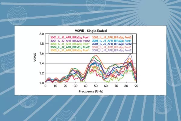
Figure 5 VSWR plot of 2-port tests of Samtec’s 1.35 mm threaded compression-mount coaxial connectors.
Testing accuracy and repeatability are major concerns for devices operating in the upper mmWave frequency range. A suitable interconnect solution should be able to provide good performance and repeatability over several installation cycles. Figure 5 plots measured VSWR for 10 samples (five tests using a two-port network analyzer), where 1.35 mm compression-mount coaxial connectors are assembled on either side of a planar transmission line. Using this method, the VSWR performance can be extracted from both the port 1 and port 2 connectors.
The results of the VSWR plot in Figure 5 show excellent performance, especially between 50 and 80 GHz. VSWR is lower than 1.2:1 at the connector’s cutoff frequency. It is important to maintain alignment during installation since connecting the test cables to the compression-mount connector can create some rotation. Anti-rotation tools can be used to hold the connector in place while the test cable is connected and disconnected. This is typically done using a wrench or a pair of pliers to counteract the force of the torque wrench used to tighten the coaxial connector to specification.
CONCLUSION
Higher data rates for networking and backhaul communications, along with higher operating frequencies for communications and sensing technologies are leading to an increased need for high frequency, precision interconnect solutions. To allow these connectors to operate at higher frequencies and interconnect densities with a minimal board footprint, the entire interconnect solution needs to be very compact. Precision alignment of the center pin of these connectors to the landing pad at these high frequencies is both challenging and a critical requirement. The visual alignment technique described and implemented in Samtec’s new threaded compression-mount connectors help address the alignment challenges associated with mmWave compression-mount connectors.