
DISRUPTIVE MMWAVE BEAMFORMING
As the inventor of the technology and founder, Lerosey decided to take a leave from academia to save the company. Besides finding cash, the most urgent matter was finding other applications for our core: electronically reconfigurable surfaces with physics-based algorithms to control them. In academia, we had studied the properties of cavities made reconfigurable with tunable metasurfaces. We used surfaces with controllable electromagnetic properties as reconfigurable boundary conditions in cavities.15–17 Several ideas emerged that were investigated with a new partner, Timothée Laurent, who brought 10 years of experience as a strategy consultant at Kearney. One of the ideas that made sense was to make the cavity leaky and use it as an electronically steerable antenna for 5G or satellite communications.
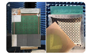
Figure 4 The proof of concept for an electronically steerable antenna using the 5 GHz RIS developed for Wi-Fi (left) and the equivalent version 2 years later at 30 GHz (right).
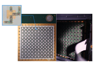
Figure 5 The first Greenerwave mmWave RIS developed for an electronically steerable antenna.
The steerable antenna works as follows: waves are injected inside the cavity using a basic source, the tunable metasurface shapes the generated wavefield inside the cavity and the field leaks out through openings in the cavity, forming a beam in a chosen direction. Jean-Baptiste Gros quickly assembled a proof of concept using a 5 GHz tunable surface designed for the Wi-Fi RIS, putting it in a metallized MacBook box with a simple monopole. The result was impressive: using a bunch of Si PIN diodes and a very simple printed circuit board design, we realized an electronically steerable antenna that could be as flat as a conventional active phased array (see Figure 4). Impressed, the French Defense Agency provided funding to apply the concept to demonstrate a beamformer around 30 GHz.
Going from GHz to mmWave was not easy, but we had our first tunable 27 to 31 GHz electromagnetic surface by the end of 2019 (see Figure 5), which used the simple binary phase shift design with dual polarization control. We assembled our first antenna at the beginning of 2020, a 10 x 10 × 2.5 cm3 prototype fed by a monopole in one of its corners (see the right hand photo in Figure 4). To realize the leaky part of the cavity, we used a semi-transparent RF mirror made of copper mesh on a substrate, which we spatially tuned to be more transmissive at the center than on the borders, which was intended to taper or apodize the beams.
We only realized the unique potential of the technology after testing it. First, we could verify that despite the small size of the antenna and the very crude binary phase control of the tunable surface, we could form beams in any direction, with directivity only a few dB below the theoretical limit. Second, the antenna could support a bandwidth only limited by the tunable surface, i.e., more than 4 GHz. We measured instantaneous bandwidths from 300 MHz to 2 GHz that could be software-controlled (see Figure 6a). Third, the scan range of the antenna was ± 70 degrees with the scan loss defined by the cosine law, with control over any polarization and its purity (see Figure 6b). This unique characteristic results from the design of the antenna: the whole field created inside the cavity radiates to the far-field through the very tiny holes of the leaky mask, outperforming phased arrays that are limited by the radiation pattern of their individual radiators. Fourth, we demonstrated the antenna could emit multiple beams at a single frequency, at different frequencies, even on orthogonal polarizations (see Figure 6c). A slightly modified antenna showed that hybrid beamforming is possible with minimal crosstalk, by sending four beams from four feeds at the same frequency. Last, the beamforming proved very robust to reducing the number of diodes inside the cavity; the sidelobes remain well controlled with 25 percent or 50 percent of the unit cells not active (see Figure 6d).
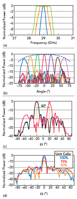
Figure 6 Electronically steerable antenna performance: tunable instantaneous bandwidth (a), scan angle and loss (b), multi-beam performance (c) and resilience to loss of unit cells (d).
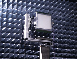
Figure 7 Ka-Band transmit antenna prototype, which established a link with the Athena-Fidus GEO satellite.
The mmWave prototype convinced us of the advantages of the technology: a flat electronically steerable antenna with hardware nearly as simple as passive phased arrays, very low power consumption and high efficiency. Beam switching is as fast as with an active phased array and has unique features such as multi-beam, multi-polarization and multi-band capabilities, all controlled by software. The antenna is conformable to any shape, compatible with any front-end design and protocol/standard agnostic because it is based on wave control.
SATCOM AND AUTOMOTIVE APPLICATIONS
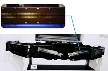
Figure 8 Tunable electromagnetic surface at 77 GHz (top) and integrated in a bumper as part of a beamforming radar (bottom).
We scaled the antenna to 30 × 30 × 2.5 cm3 and engineered a more homogeneous feed consisting of a leaky waveguide around the perimeter of the cavity. The new design, which required a few iterations and was completed mid-2021, covered 27 to 31 GHz, consumed approximately 30 W and had the same properties as the first prototype (see Figure 7). It established a datalink with the French Defense Agency GEO satellite Athena-Fidus, leading the French Defense Agency (AID) and French Space Center (CNES) to fund further development of the Ka-Band antenna. Greenerwave is funding development of a Ku-Band version, which is planned to be commercialized by the end of 2023. Because of the simplicity of the hardware, the antenna solves a significant problem each mega-constellation operator faces: the price of the ground terminal.
Our first 5 GHz proof of concept steerable antenna was also interesting to a French automotive supplier, Plastic Omnium. Its chief innovation officer saw the potential of the simple beamforming technology for mass market automotive applications, turning the conventional 77 GHz radar into a high-resolution 4D imaging radar. Embedded in Plastic Omnium’s large vehicle body panels, an antenna built on Greenerwave’s experience in ultrasound and optics imaging,18 could be a game changer in the automotive market. A simple proof of concept at 7 GHz using our beamforming technology with time multiplexing and homemade algorithms turned a 1Tx/1Rx radar chipset into an imaging device. The performance of this prototype led to a more ambitious project to replicate the technology in the automotive radar band at 77 GHz, transforming an off-the-shelf 3Tx/4Rx radar chipset into a 4D imaging radar. The success of the 77 GHz prototype led to our current effort: integrating several beamformers with unique imaging algorithms in a bumper (see Figure 8), intended to transform a conventional radar chipset into a cost effective, low-power, multi-mode 4D imaging radar.
THE FUTURE
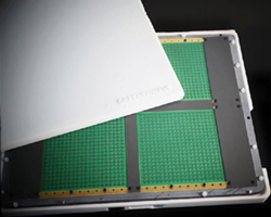
Figure 9 mmWave RIS for 5G, demonstrated as a passive access point extender and tested by NTT Docomo on a 5G base station.
Four years after a complete pivot and new start with a single employee, Greenerwave now employs more than 40, has multiple public contracts and private customers and a growing patent portfolio of some 12 patent families on various applications. Our near-term goal is to launch our satcom antennas, which requires a series A fundraising round. Meanwhile, we continue to explore business models from licensing to products, partnering with companies to apply our unique technology to antennas, automotive radar and RFID—an application without technical barriers and worthy of a future article.