
5G is the wireless communications standard for the next decade. With frequencies to 88 GHz and peak transfer rates of 10 Gbps, 5G has attracted significant investment across the supply chain, from the semiconductor suppliers through the mobile operators to application developers. From the measurement viewpoint, measuring the RF performance of the 5G base station to the 3GPP standards has largely been addressed except for assessing compliance with the electromagnetic field (EMF) immissions standards for base stations using beamforming. This article addresses the challenges posed by beamforming antennas.
To ensure public safety, Germany and most other countries require an EMF immission evaluation of cellular base stations, beginning when new transmitting equipment is submitted to regulatory agencies for approval. The aim is to determine the worst case (i.e., greatest) field strength people can be exposed to. If this is below the health and safety limits, the equipment can be approved and assumed to operate safely in all situations. Theoretically, to assess immissions, the system operator would run the base station and antennas at full power for the duration of the EMF measurement. Practically, this presents a problem outside of a lab or testing environment. The network operator would have to isolate the system from live operation and test it by itself, offline and at full power. This is not something a government authority could demand from an operator and would be contrary to an independent, unannounced external check of the immissions of a system. If the operator is unaware the system is being measured, the values will be trustworthy and no one can reasonably claim the equipment was manipulated to obtain an acceptable result.
MEASURING IMMISSIONS
To assess the immissions of an installation, the regulations (e.g., BImSchV in Germany) stipulate that the electric and magnetic field strength at the maximum operational load (i.e., power) are to be determined. In the event the maximum cannot be set during the measurement, a suitable extrapolation to the maximum is allowed.
The measurement is where “the wheat and the chaff are separated.” First, the signaling, which is always transmitted at a constant power level, must be separated from the data traffic (see Figure 1). The signaling signal is used by a cellphone to synchronize to the network, and it provides the measurement with a reference level for extrapolation. However, the maximum possible immission from the base station is radiated by the traffic, not the signaling. So when measuring immissions, the test instrument must be able to separate the signaling from the composite signal.
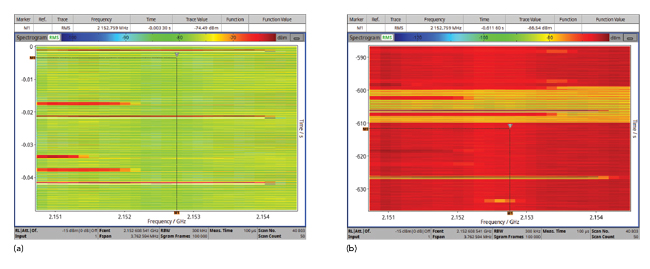
Figure 1 Spectrograms of 5G transmissions: signaling (a) and signaling with traffic (b).
How this is done has evolved over the generations of cellular technology (see Table 1). With GSM, it was possible to separate the signaling channels by frequency. For the extrapolation, a technician tuned the measuring instrument to record the frequencies that contained only the signaling signal. With the next generation, UMTS, and the adoption of code division multiple access (CDMA), it was not possible to separate the signaling and traffic by frequency; the old frequency selective test equipment could not distinguish between the signal types. With coding, the signal transports information uniquely assigned to a specific radio cell. Code-selective measurements replaced frequency selective measurements for determining EMF immissions, requiring the testers to decode the coding.
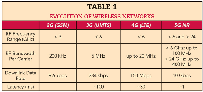
Code-selective measurement methods are now indispensable. Only with this method can testing distinguish between the immissions from two different base stations operated by the same service provider or the individual sectors of a base station, since each sector has a unique code called the physical cell ID.
Narda STS has a heritage developing EMF test and measurement equipment to assess compliance with the standards for safety, environmental and personal protection, and the Narda STS SRM-3006 is one such instrument (see Figure 2). It displays the EMF strength as a percentage of the regulatory limits or standards and covers all the cellular bands, including the new 5G bands in frequency ranges 1 (FR1) and, using two new 5G downconverter antennas, also 2 (FR2).
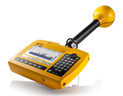
Figure 2 The Narda SRM-3006 for frequency and code selective immission measurements of cellular signals.
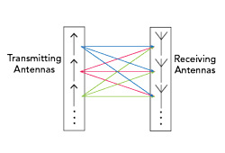
Figure 3 By increasing the number of transmit and receive antennas, MIMO and mMIMO increase the sector throughput and capacity density of a base station.
BEAMFORMING COMPLEXITY
The development and adoption of MIMO and massive MIMO (mMIMO) antenna systems has complicated immissions testing because a beamforming antenna has different antenna patterns and gains for traffic and signaling.
mMIMO provides spatial multiplexing and concentrates the transmitter’s power into one or more beams that increase the overall data throughput and system efficiency (see Figure 3). Initial 5G deployments seem to have standardized around 32 or 64 active antenna elements, although that number can potentially grow to between 128 and 1024 antenna elements.
mMIMO directs the output power of the base station to individual cellphones using multi-user beamforming (MUBF), i.e., forming or shaping the antenna pattern by managing the phase differences among the signals applied to the antenna elements. mMIMO uses beam steering to point the antenna beams to focus on a user or group of users. Beamforming and beam steering increase the link range and reduce interference between radio cells, optimizing the radio coverage for smaller areas of a sector. Focusing the transmitted power on the users also increases the efficiency of the base station.
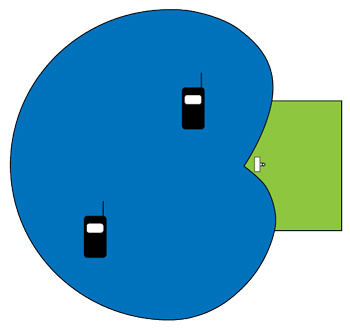
Figure 4 Typical sector coverage for a base station sector without beamforming.
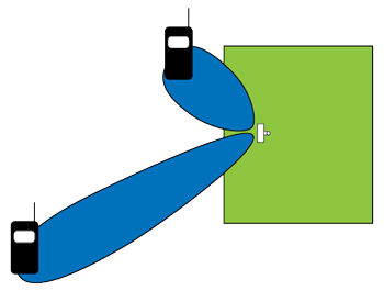
Figure 5 Notional sector coverage with beamforming.
With beamforming, the antenna no longer covers a 120-degree sector with a single wide beam (see Figure 4). The base station focuses a beam or several beams on the users (see Figure 5). To determine the optimum direction for a user, the base station will transmit the signaling beam in several directions, such as seven horizontal directions 17 degrees apart (i.e., 120/7). As the base station steps through the signaling beams, a receiving cellphone measures the strength of each signal and tells the base station which beam has the best quality. The base station uses this as the best direction for the user until the user moves or the propagation changes.
Beamforming is typically used at the upper frequency cellular bands, i.e., above 2.5 GHz. The lower bands—700, 800 and 900 MHz—are largely used in rural areas because of the lower population density and superior propagation, yielding a longer range between towers. Data throughput is not likely to reach network capacity. Areas with high population density, such as inner cities or exhibition centers, demand higher capacity and data rates. In such cases, base stations tend to use higher frequency bands, where the bandwidth and data capacity are greater. Although the coverage range is less, the cumulative result is more data capacity in the network, which can be further increased with mMIMO.
Implementing beamforming antennas is more practical at the higher bands, where the half-wavelength spacing between the antenna elements results in compact antennas—80 × 80 or 90 × 90 cm—that can be mounted on a rooftop or tower by one or two people. In comparison, a 900 MHz beamforming antenna would be some 3 m², too large for most installations.
BEAMFORMING ANTENNA IMMISSIONS
Determining the immissions of a 5G base station without beamforming requires measuring the signaling signal and extrapolating the result to the entire bandwidth. With beamforming, the method requires an additional beamforming factor, derived from the difference between the antenna patterns for the signaling and traffic signals at the measurement location. The two antenna patterns are provided by the operator, and the difference at the measurement location is used with the signaling measurement to determine the maximum traffic immission value, i.e., the maximum possible immission of the base station.
Even with beamforming, the signaling from the base station is radiated using a broadcast beam, which has a wider beamwidth than the traffic signals responsible for the immission. The broadcast beam is measured, and the result is extrapolated using the beamforming factor to give the field strength if the traffic were solely directed to the measurement point. For time-division duplexing networks, the uplink/downlink configuration is another factor that must be included in the extrapolation.
One of the measurement challenges is knowing the location of the measurement point with respect to the direction of the base station being measured. This is often determined the “old-fashioned way,” using a map with a compass, rangefinder and protractor to determine the distance, direction, azimuth and elevation of the measurement point relative to the antenna. The test technician uses this location to determine the antenna gains for the broadcast and traffic beams, which is provided by the operator. The gain difference is part of the immission calculation.
Another challenge unique to beamforming antennas is knowing whether the beam is focusing on the measurement point when the measurement is made, as reliable information about beam pointing is unavailable. Techniques are needed that can extrapolate to the maximum system state from the signaling and address the uncertainty of a moving, narrow lobe. A simple solution would be forcing the beam to point at the measurement location. This could be done using a special handset that requests a massive data download, triggering the transmitter to direct a full power beam toward the handset. The maximum field strength could then be measured. However, this method only works if the measuring device is the only receiver in the cell. With another active user geographically separated, as shown in Figure 5, a second beam will be formed that will reduce the power from the measurement point and lead to an incorrect immission measurement. This simple method is not suitable for a cell operating normally and is not appropriate if the measurement is to be independent and unannounced, which is usually the intention.
SUMMARY
Measuring immissions for 5G NR is not very different from the approach used with earlier cellular generations, i.e., GSM, UMTS and LTE. Measuring instantaneous EMF immissions of a base station is comparatively simple. It becomes challenging when the immission evaluation is to be based on the maximum system state, as required in Germany, for example. Then it is necessary to extrapolate the actual measured field strengths to the maximum possible value, which can only be accomplished by using code-selective measurements. These were developed with the transition from GSM to UMTS and apply directly to 5G NR base stations that do not use beamforming. For 5G systems that use MIMO or mMIMO, typically in the bands above 2.5 GHz, the measurement must account for the added gain of the steered beams. The test approaches and standards for such beamforming immissions measurements are being finalized by the regulatory bodies in several countries.