
Initially, Russia delivered two LEO Cospas satellites placed in near-polar orbits at 1,000 km altitude equipped with SAR instrumentation at 406 MHz. The U.S. delivered two NOAA meteorological satellites of the Sarsat system placed in sun-synchronous polar orbits at about 850 km altitude equipped with SAR instrumentation at 406 MHz, supplied by Canada and France. Each PEO satellite makes a complete orbit of the earth around the poles in about 100 minutes, traveling at a velocity of 7 km/s.
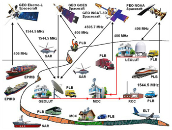
Figure 6 Cospas-Sarsat LEOSAR and GEOSAR operations.
The LEOSAR concept exploits the Doppler shift resulting from relative motion between the distress transmitter and the polar orbiting satellite. A successful alert requires at least one satellite pass over the distress area to detect a signal and locate the position of the emergency transmitter. In some cases, a second pass may be required to resolve ambiguity.
Satellites in the LEOSAR subsegment do not provide continuous coverage. This results in possible delays in the reception of the distress alert. The waiting time for detection by the LEOSAR subsegment is greater in equatorial regions than at higher latitudes. Thus, as shown in Figure 5 and Figure 6, LEOSAR and GEOSAR satellite transponders work in three ways:
1. UHF 406 MHz LEOSAR Local Mode – When the LEOSAR satellite receives 406 MHz distress signals, the onboard SAR processor (SARP) recovers the digital data from the beacon signal, measures the Doppler shift and time-tags the information. The result of this processing is formatted as digital data and transferred to the downlink for transmission to any LEOLUT in view.
2. UHF 406 MHz LEOSAR Global Mode – The 406 MHz SARP system provides near global coverage by storing data derived from the onboard processing of beacon signals in the LEOSAR spacecraft memory unit. The content of the memory is continuously broadcast on the satellite downlink. Each beacon can be located by a LEOLUT terminal, which tracks the satellite and provides global coverage with ground segment processing redundancy. The 406 MHz global mode also offers an additional advantage over the local mode with respect to alerting time when the beacon is in a LUT coverage area. As the beacon message is recorded in the satellite memory at the first satellite pass in the visibility of the beacon, the total processing time can be considerably reduced through the broadcast of the satellite beacon message to the first available LUT.
3. UHF 406 MHz GEOSAR Global Mode – Three GEO satellites equally spaced in longitude can provide continuous coverage of the globe between approximately 70 degrees north and 70 degrees south, excluding the polar regions. As the GEOSAR satellite remains fixed relative to the earth, there is no Doppler effect, so radio beacons need the GNSS receiver to provide a determination of the distress position. Location of distress is available only if beacon has a GNSS receiver chip and encodes the location in the beacon message. As shown in Figure 6, the detected distress signals are relayed by LEO and GEO satellites on 1544.5 MHz or 4505.7 MHz (INSAT only) to the appropriate GEOLUT station, where the signals are processed to determine the location of the satellite beacons and/or a mobile in distress.3,5,6,7,8
MEOSAR Space Segment
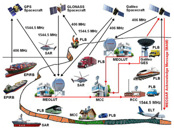
Figure 7 MEOSAR operation.
The U.S., Russia and the European Commission/ESA have designed the Cospas-Sarsat subsegment that includes 406 MHz SAR repeater instruments on their respective MEO satellites together with GNSS networks of current U.S. GPS and Russian GLONASS, including forthcoming European Galileo. In such a way, an implementation plan for integrating MEOSAR components into the Cospas-Sarsat system (document C/S R.012) was developed in 2006 and can be downloaded from the Cospas-Sarsat website.
An innovative MEOLUT system will provide future service, such as: 1) Near global MEOSAR coverage with accurate independent location capability (no reliance on a navigation receiver), 2) Robust distress beacon-to-satellite communication links and a high level of satellite redundancy and availability and 3) Resilience to distress beacon-to-satellite link obstructions, i.e. satellite motion alleviates line-of-sight beacon-to-satellite blockages. Therefore, one of the main goals of the new MEOSAR system is to determine beacon location within 5 km, 95 percent of the time and within 10 minutes via 72 MEOSAR satellites positioned at MEO altitude.
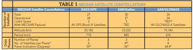
Supporters of the Cospas-Sarsat system are preparing to evaluate a new capability of MEOSAR satellites, consisting of SAR transponders aboard navigation satellites of Europe, Russia and the U.S. (see Figure 7). All distress signals sent from 406 MHz EPIRP, PLB and ELT are detected by the Distress Alerting Satellite System (DASS) GPS, GLONASS or Galileo GNSS transponders and resent to MEOLUT stations. From MEOLUT stations, position data goes to the MCC, RCC and RCC, which give instructions to SAR ships and helicopters. In that MEOSAR network, Galileo ground earth station (GES) can send MAM as a confirmation of receipt only via Galileo satellites. The MEOSAR satellites orbit the earth at altitudes ranging from 19,000 to 24,000 km (see Table 1).3,4,8,9,10
USER SEGMENT
The Cospas-Sarsat user segment contains three radio beacons: EPIRB for ships, PLB for personal use or land vehicles (road and rails) and ELT for aeronautics applications. Future users have a list of all manufacturers of emergency satellite beacons presented in the Cospas-Sarsat system data brochure. Soon after purchasing a new or used emergency beacon it is necessary to register it with an authority indicating contact details and physical address.

Figure 8 Cospas-Sarsat EPIRB (a), PLB (b) and ELT (c) satellite beacons. Source: Joton and Orolia Kannad.
1. Jotron Tron 60 S/GPS EPIRB – The Tron 60 S/GPS EPIRB (see Figure 8a) is developed to meet the regulations and rules for use on large vessels and life rafts in the maritime service in SAR operations at sea. The author recommends that the aviation community use this type of EPIRB for installation onboard long-haul aircraft. It is buoyant and has water activated contacts that will start distress transmissions if deployed into water. The 60 S/GPS is currently available with two different brackets, one manual type and one float free version. The purpose of the Tron 60 S/GPS is to give a primary alarm to the SAR authorities. The EPIRB gives an immediate alarm when activated, transmitting the ID of the ship in distress.
2. Orolia Kannad XS-4 PLB/With GPS – This beacon (see Figure 8b) can be used for personal rescue primarily for pilots and aircraft crews, for the needs of various vehicles traveling in remote environments and for personal services. It has a three-stage operation: 1) lift the flip cover, 2) pull the anti-tamper cover to deploy the antenna and 3) push and hold the ON button to activate the PLB. Once activated it works for at least 24 hours. It is perfect to carry in addition to the onboard aircraft and other mobile radios.
3. Orolia Kannad 406 AS ELT – This survival beacon is intended to be removed from the aircraft and used to assist SAR teams in locating survivors of a crash at sea and on the ground (Figure 8c). Thanks to its small size and light weight, it fits easily inside a life-raft and it is supplied with a floating collar to enable the ELT to float upright if used in water (like the maritime EPIRB units). Its floating collar can be removed if the ELT is attached to a liferaft or any buoyant part. It is a standalone device equipped with an auxiliary antenna and activated manually by survivors or automatically by a “water switch sensor” when in contact with seawater. It is made of molded plastic with excellent mechanical resistance (ASA/PC, light yellow color). The housing is designed to be easily taken in one hand, and a tether is supplied to tie the ELT to a liferaft. 4,10,11,12,13
GROUND SEGMENT
The Cospas-Sarsat ground segment contains LUT ground stations, such as LEOLUT, GEOLUT and MEOLUT and MCC formations associated with RCC terminals and SAR infrastructures of ships, aircraft and helicopters for SAR missions.
1. Honeywell LEOLUT Receiver and Antenna – The LEOLUT unit single or dual LUT configuration (see Figure 9a) combines LEO/GEO processing capability internalized satellite orbit data. This is a fully automated high performance LEOLUT that receives and processes distress signals from Cospas-Sarsat satellites and distributes location coordinates to the MCC. It maintains satellite orbit data internally, can be configured in a dual configuration and is the only LUT that can perform combined LEO and GEO data processing. Two methods are used to update the orbit: 1) tracking the downlink carrier to provide a Doppler signal using the LUT location as a reference and 2) using local calibration platforms operating at 406 MHz with accurately known locations. The LEOLUT antenna is a phased array that allows the LUT receiver to track satellites (see Figure 9b). It is a lightweight, mast or roof-mounted antenna with digitally controlled motors to provide the entire range of motion required to track the Cospas-Sarsat satellites.
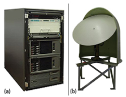
Figure 9 New generation LEOLUT (a) and antenna (b). Source: Honeywell.
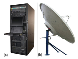
Figure 10 New generation GEOLUT (a) and antenna (b). Source: Honeywell..
2. Honeywell GEOLUT 600 GES – This model is a fully configurable ground terminal dedicated to meet SAR needs and exceeds distress data analysis requirements (see Figure 10a). Combined with the LEOLUT 600, it can offer comprehensive SAR integration with unmatched response capabilities provided by the dual processing power of the LEO-GEO system. It provides rapid notification of 406 MHz distress beacon activations to SAR authorities. Using advanced signal processing technology and custom-designed software, the GEOLUT station offers 24-hour automatic monitoring of alerts over a large territory. In conjunction with LEOLUT data, the dual LEO-GEO system provides unrivaled processing capabilities to optimize beacon location accuracy and SAR response time. The LUT hardware comprises an HP processor, GPS clock and Comtech antenna (see Figure 10b). The GEOLUT antenna is a fixed parabolic dish that allows the GEOLUT to receive distress alerts relayed through a single GEOSAR satellite.
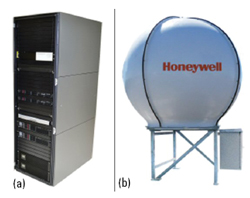
Figure 11 MEOLUT (a) with antenna (b). Source: Honeywell.

Figure 12 Cospas-Sarsat MCC terminal. Source: Cospas-Sarsat
3. Honeywell MEOLUT-600 Station – This MEOSAR station (see Figure 11a) process 406 MHz distress alerts sent by the EPIRB, PLB and ELT beacons over next-generation GPS, GLONASS and Galileo MEO satellites and provides rapid notification to SAR authorities worldwide. It is part of an integrated Cospas-Sarsat MEOSAR solution developed by Honeywell Global Tracking, which bridges the existing LEO/LEO infrastructures and can confirm the location of an emergency alert within seconds. Its antenna (see Figure 11b) is a 2.3 m (7.5 ft) mesh dish with radome that allows MEOLUT station to track MEOSAR satellite constellations.3,4,11,14,15
CONTROL CENTERS
The Cospas-Sarsat mission is to provide MCC and TCC terminals to coordinate between LUT stations and SAR forces.
MCCs
Cospas-Sarsat MCC terminals have been set up in most countries that operate at least one LUT (see Figure 12). Their main MCC functions are to: 1) Collect, store and sort the data from all LUT stations and other MCCs and 2) Provide data exchange within the entire Cospas-Sarsat system and distribute alert and location data to the associated RCC or SPOC. Each MCC is responsible for distributing all alert data for distresses located in its service area (SA). An MCC SA includes aeronautical and maritime SAR regions in which the national authorities facilitate or provide SAR services and includes regions of other countries that have appropriate agreements for the provision of Cospas-Sarsat alert data.
RCCs
The SARMaster solution provides comprehensive management of Cospas-Sarsat alerts. Alerts messages are displayed on the Geographic Information System while associated attribute information, such as frequency, time and search region of responsibility, is shown in a textual view. The TSi RCC workstation is internet enabled, putting the vast resources of the internet at the fingertips of the SAR mission planner. Several features of the RCC workstation, including weather, satellite imagery and SAR information, are automatically updated from the internet. Data and information flowing into and out of the workstation are shown in Figure 13. The Precision SAR Manager is a full-featured SAR management system that provides crucial, time-critical information to SAR personnel, resulting in safe and successful rescues. It ideally functions as an RCC workstation, communicating with MCC units or other national or international sites to receive distress calls and conduct a rescue. It also contains cutting-edge software for general SAR mission planning and analysis, resulting in a powerful SAR management system even without the benefit of Cospas-Sarsat.3, 4,11,16
CONCLUSION

Figure 13 Cospas-Sarsat RCC workstation block diagram. Source: Cospas-Sarsat.
The global SAR mission is a complex ecosystem of products, technologies and personnel with one universal goal—to save lives. The existing Cospas-Sarsat LEOSAR, MEOSAR and GEOSAR satellite network has saved five lives a day for the last 30 years. As the awareness and understanding of this ecosystem increases, from the moment of sending a distress alert to satellite connectivity, rescue coordination and solutions are increasing, so it will be possible to see new emerging applications, innovations and procedures that will save even more time and cost, all devoted to the mission of saving more lives.
References
- Utilisation des Satellites pour les Recherches et le Sauvetage, Cepadues, SNES, 1984.
- COSPAS-SARSAT System Documentation, Cospas-Sarsat, 2001.
- Cospas-Sarsat, Web. http://www.cospas-sarsat.int/en/.
- D. S. Ilcev, Global Mobile Satellite Communications for Maritime, Land and Aeronautical Applications, Vol. 1 & 2, 2016/2017.
- J. King, Description of the Cospas-Sarsat Space Segment, 2006.
- Introduction to the COSPAS-SARSAT System, 2015.
- Cospas-Sarsat LEOSAR and GEOSAR Systems, 2010.
- L. Tetley and D. Calcutt, Understanding GMDSS, 1994.
- Cospas-Sarsat MEOSAR Implementation Plan, Cospas-Sarsat, 2012.
- COSPAS-SARSAT System Monitoring and Reporting, 2015.
- D. S. Ilcev, Mobile Distress and Safety System, Manual, DUT, Durban University of Technology, 2011.
- Jotron, Web, https://jotron.com.
- Orolia, Web, https://www.orolia.com.
- Cospas-Sarsat LEOLUT, GEOLUT and MEOSAR Systems, 2018.
- Honeywell, Web. https://www.honeywell.com.
- Mission and Rescue Control Centres, Cospas-Sarsat, 2019.
Professor Dimov Stojce Ilcev is a research leader and founder of the Space Science Centre for research and postgraduate studies at Durban University of Technology. He has three B.S. degrees in Radio, Nautical Science and Maritime Electronics and Communications. He received his M.S. and Ph.D. degrees in Mobile Satellite Communications and Navigation as well. Prof. Ilcev also holds the certificates for Radio operator 1st class (Morse), for GMDSS 1st class Radio Electronic Operator and Maintainer and for Master Mariner without Limitations. He is the author of several books on mobile radio and satellite CNS, DVB-RCS, satellite asset tracking and stratospheric platform systems for maritime, land (road and railways) and aeronautical applications.