
The growing volume of data traffic to and from wireless devices calls for high bandwidth to connect users to the internet. Two 5 GHz frequency bands are available in E-Band for commercial very high throughput satellite (VHTS) communication systems. However, adopting these high frequencies makes RF component and subsystem development challenging for the satellite communications (satcom) system as well as the test and measurement (T&M) equipment and setups for working in E-Band. At these frequencies, propagation and atmospheric attenuation require higher power and lower noise figure components for the communication links. The mmWave components and subsystems developed for the ground gateway and spacecraft are significantly more complicated at E-Band because RF components suitable for satcom links need to be developed and qualified for the space portion of the system. Signal generation, adequate linear RF power in the band, fade mitigation techniques, the physical sizes of the RF components and regulatory challenges are a few of the elements to be examined.
This article discusses the RF advantages and complexities of operating wide bandwidth satcom systems in the lower and upper E-Band (i.e., 71 to 76 and 81 to 86 GHz, respectively). For this discussion, wide bandwidth refers to channels with instantaneous modulation bandwidth of 500 MHz to 2 GHz, which are needed to support Tbps satcom. Hughes Network Systems (HUGHES®), a leader in broadband satcom systems, is currently researching VHTS operation in E-Band, and this article is based on this work, supported by component and T&M suppliers.
MOTIVATION TO USE E-BAND
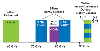
Figure 1 V-, E- and W-Band frequencies. Source: Rohde & Schwarz.
Systems designed at 70 and 80 GHz can tap 10 GHz of bandwidth—far more than is currently available at the lower point-to-point transmission frequencies from 4 to 51 GHz. Antennas at these higher frequencies create highly directive pencil beams that provide high gain, to compensate for high path loss, and high discrimination, enabling gateways to be tightly packed into favorable rain zones without suffering from co-frequency interference. Existing Q-, V- and Ka-Band systems are spectrally crowded, with limited bandwidth available and suitable for VHTS communication systems.1
To use E-Band, licensees only pay a reasonably small administrative fee to the regulating authorities. This “light” licensing model provides full interference protection and makes the economics of Tbps connectivity attractive for commercial VHTS communication systems. This, along with the antenna advantages mentioned, has spurred research into the commercial viability of using E-Band to provide Gbps connectivity at a level complementing fiber optic cable.
Figure 1 compares several mmWave frequency bands considered for VHTS communications links. E-Band is the logical candidate for gateways, Q-Band for the forward downlink:
- 5 GHz contiguous blocks have no known regulatory constraints
- E-Band is the logical next band for feeder links after V-Band
- Q-Band is logical next band for user links after Ka-Band.
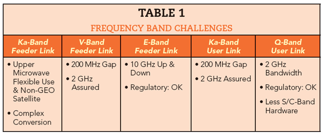
Table 1 shows the characteristics for the feeder (gateway) and user (terminal) links for Ka-, V-, Q- and E-Band. The disjointed uplink and downlink at Ka-Band add excessive hardware to the system, which increases spacecraft mass, occupies panel space and lowers system reliability.
While E-Band is attractive because of the available bandwidth and light licensing, it poses significant complexities for the uplink and downlink:
- Component and subsystem technology performance and commercial availability
- Propagation losses: rain and free-space loss
- Antenna design for the ground gateway and spacecraft
- T&M equipment and measurements.
COMPONENTS AND SUBSYSTEM CAPABILITY
The state of E-Band technologies for commercial Tbps satcom systems is a fundamental question. Although many E-Band components have been developed for automotive radar and cellular infrastructure, they are not space-qualified. E-Band semiconductor and passive components must be qualified for spacecraft - in some cases redesigned for satellites - and a viable supply chain developed to support this. For the gateway, some existing RF components will work; however, the high power amplifier (PA), antenna and feed losses will be challenges that need to be addressed for commercial Tbps systems, particularly increasing the output power and ensuring a mature technology.
As noted, a significant issue will be whether suppliers will participate in the E-Band satcom arena, despite supplying the automotive radar, EMC and military market segments with commercial components in the 60 to 90 GHz range. The challenges are meeting the satcom link performance requirements and qualifying the technologies and components for space.
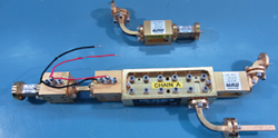
Figure 2 Example of an E-Band signal chain.
A few suppliers do market space-qualified E-Band subsystems because there is some demand for such components. Because of the wavelengths at E-Band, the components typically use WR-12 waveguide requiring precise cavity dimensioning and fabrication. The gap transition tolerances must be extremely small to avoid excessive VSWR and insertion losses. Figure 2 shows a couple of typical E-Band subsystems, integrating filters, amplifiers and waveguide sections.
We predict that InP low noise amplifier (LNA) technology or some exotic heterojunction high bandgap materials with super low noise figure will be required in both the spacecraft and gateways for E-Band systems. Hughes’ estimates a 2 to 3 dB noise figure is needed in the gateway, possibly relaxed to 4 dB in the spacecraft. Based on the component and antenna requirements, the technologies being proposed for the PAs and LNAs at both ends will be tube based, possibly some solid-state PAs. High-power, linear tubes will be considered, and GaN may play a role in the PA, depending on timing. Hughes is currently conducting detailed tradeoffs to determine the best technologies and the manufacturers able to support space-qualified E-Band Tbps systems.
This same assessment process applies to the gateway and spacecraft antennas. Composite materials with very low surface roughness are feasible for the antennas as long as the tolerances are precise.
PROPAGATION LOSSES
The free-space path loss (FSPL) is the expected attenuation of an electromagnetic wave as it travels away from the source. In the far field, it increases proportional to the square of the frequency:

where d is the distance, f the frequency and c the speed of light.
The satellite and ground antenna gain also increases proportional to the square of the frequency:
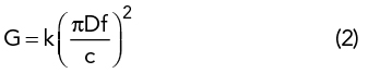
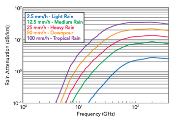
Figure 3 Rain attenuation vs. rainfall vs. frequency.2
where G is the gain expressed as a ratio, D is the antenna diameter and k is the antenna efficiency factor. Since there are two antennas in the gateway link—at the satellite and on the ground—as frequency increases, the increase in the gain of one antenna will compensate for the FSPL increase. The increase in the other antenna’s gain will at least partially compensate for the increased loss due to rain (see Figure 3). At E-Band, light rain will add 2 dB/km atmospheric attenuation, while links in tropical regions must be designed for approximately 30 dB/km.