
A high-power, low loss radial waveguide combiner design was based on two bandpass filters and two radial waveguide structures connected by 12 rectangular waveguides. The transverse electromagnetic (TEM) mode coaxial waveguide filters had greater than 99 percent transmission efficiency across the 300 MHz bandwidth. Long pulse power combining measurements at 9.38 and 9.7 GHz demonstrated gigawatt (GW) power handling capacity and high transmission efficiency.
High-power microwave (HPM) has emerged in recent years with new applications and innovative ways to approach existing applications in areas such as directed-energy weapons, plasma heating, atmospheric monitoring and space.1-4 Narrowband HPM devices have been widely developed and GW level outputs have been achieved experimentally.5,6 Owing to the limitation of physics and technologies, however, further improvement in the output power capability of a single HPM source has encountered bottlenecks.7,8 To overcome this, an effective approach to obtain higher output power is using waveguide power combining technologies.9-11 Based on polarization orientation of the combined microwaves, these technologies can be divided into cross-polarization synthesis and co-polarization synthesis. For cross-polarization synthesis, a T-junction combiner with two kinds of metal plates and a cross-junction combiner have been verified by simulation and experiment.9,10 For co-polarization synthesis, multiplexers based on waveguide filters have been widely adopted.
An S-Band multiplexer with three rectangular waveguide filters was described by Li et al.11 Within a 100 MHz passband, the energy efficiency of the diplexer was as high as 95 percent. With 1 GW of incident microwave power, however, the maximum electric field (E-field) of the entire device exceeded 500 kV/cm, causing E-field breakdown. It also suffered from issues such as large size, dispersion and diffraction. In this work, a high-power, radial waveguide X-Band combiner was designed using two radial waveguide structures and two wideband filters. Its transmission characteristics were investigated through theoretical analysis and simulation. Long pulse measurements were conducted without microwave breakdown. Experimental results agreed with the analysis, which indicates a transmission efficiency greater than 95 percent within the 300 MHz passband, with power handling greater than 1.5 GW.
DESIGN AND SIMULATION
The combiner consists of six parts (see Figure 1): 9.4 GHz waveguide filter, 90-degree coaxial waveguide bend, 9.7 GHz waveguide filter, branching structure, multi-way transmission structure and combining structure. The 9.7 GHz TEM microwave signal travels through the 9.7 GHz filter and is reflected by the 9.4 GHz filter, forming standing waves. Taking advantage of magnetic coupling in the branching structure with 12 rectangular waveguide ports, the standing waves are extracted and propagate through the 12-path transmission structure. Outputs from the 12 paths are added in the combining structure. The 9.4 GHz signal is input into the combiner via a 90-degree bend and is similarly processed.
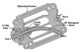
Figure 1 High-power combiner.
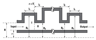
Figure 2 Azimuthally symmetric coaxial filter structure.
The performance of the bandpass filters determines the device threshold. Therefore, an azimuthally symmetric coaxial filter structure is used to realize high-power and low loss (see Figure 2). It can be regarded as multiple step discontinuities isolated by short coaxial waveguides. Mode matching theory was used to analyze the step discontinuities in the coaxial waveguide to obtain the structure’s scattering matrix.12,13 Based on mode matching theory, only the TEM and TM0m mode can be excited when the TEM mode is injected. The mode matching coefficients at the junction (z = 0) are shown by Equations 1 through 3, respectively.


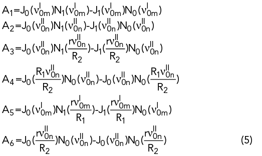
where βi0p is the propagation constant of TM0p mode in region i, νi0p is the pth root of Equation 4, with κi0p the cutoff wave number of the TM0p mode in region i. Ai is shown in Equation 5:

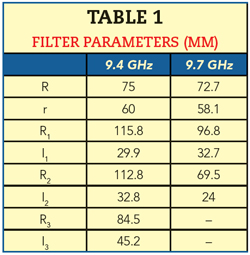
Corrugated coaxial waveguide filters with 9.4 and 9.7 GHz center frequencies, respectively, were designed based on the above analysis. The total lengths of both filters are less than 180 mm. To ensure the TM0m mode degenerates in the radial waveguide, the radius of the input and output ports of the filters were set at 75 and 72.7 mm, respectively, with the radius of the inner cores at 60 and 58.1 mm. The dimensions of the coaxial waveguide filter parameters are listed in Table 1.