

Figure 1 Simultaneously transmitting and receiving at the same frequency is a capability required by many military platforms.
Nearly all RF systems require the capability to both transmit and receive. Even receive-only systems often coexist with other transmitters located on the same platform (see Figure 1). To optimally use the available bandwidth, it is highly desirable to be able to transmit and receive at the same time on the same frequency. This capability is usually referred to as simultaneous transmit and receive (STAR) or in-band full-duplex (IBFD). The unfortunate reality is, in most cases, the laws of physics prevent simultaneous, same frequency operation of co-located transmitters and receivers. Transmit (Tx) and receive (Rx) signal levels can differ by more than 10 orders of magnitude, requiring > 100 dB isolation between Tx and Rx channels to achieve true STAR/IBFD operation. Tx powers can range from +20 to +50 dBm, while Rx signal power levels range from -100 to -50 dBm. Typical isolation between physically separate Tx and Rx antennas—or through antenna interface circuits such as circulators—falls far short of the required isolation. In the worst case, high-power Tx leakage at the receive input can physically damage sensitive RF electronics if the Tx power is high and the isolation between antennas is poor. This is particularly problematic at mmWave frequencies and in systems with wideband data converters, which tend to have inherently low immunity to high-power signals. In such situations, the strength of the self-interference must be reduced in the analog domain to prevent damage to the hardware. With lower Tx power or higher antenna isolation, the self-interference signal strength may be low enough to not cause damage to the electronic components, but it can still substantially degrade receiver performance. Transmitter interference can exceed the receiver’s dynamic range by orders of magnitude, causing a host of problems such as gain compression, intermodulation distortion and increased noise figure, decreasing the receiver’s sensitivity and dynamic range. The strength of the self-interference must be reduced in the analog domain to prevent these non-ideal effects. Even if the non-ideal hardware effects can be prevented, the transmitter leakage can still be orders of magnitude higher than the signals of interest, degrading the signal-to-noise ratio and masking the desired signals.
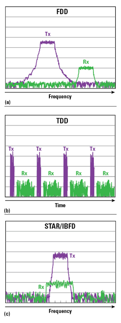
Figure 2 Frequency domain (a) and time domain (b) duplexing cannot use the full information capacity of the bandwidth in a channel. Theoretically, STAR at the same frequency (c) provides twice the channel capacity of half-duplex systems.
Overall, systems must have 50 to 80 dB Tx/Rx isolation to prevent distortion and possible damage to the receiver front-end and 100 to 150 dB isolation to ensure Tx leakage is below the noise floor of the receiver. As physical antenna isolation alone rarely provides this isolation, the remaining options to achieve "peaceful” Tx/Rx coexistence are:
- Reduce the transmit power level or add attenuation to the receiver
- Use separate frequencies for Tx and Rx with RF filtering to achieve the required isolation, i.e., frequency-domain duplexing (FDD), illustrated in Figure 2a
- Restrict Tx and Rx to non-overlapping timeslots, i.e., time-domain duplexing (TDD), shown in Figure 2b
- Apply knowledge of the Tx signal to actively cancel transmitter leakage, i.e., STAR/IBFD (see Figure 2c).
Simply reducing the Tx power or adding attenuation to the receiver severely compromises system capabilities and are usually not acceptable options. However, in certain situations —particularly those severely size, weight and power constrained - this may be the only viable option.
FDD and TDD are the most common methods today, used in nearly all communication systems, radars and other transceivers. FDD systems use separate predefined frequency bands for the Tx and Rx channels (see Figure 2a). RF filters provide Tx/Rx isolation to prevent saturation of the RF front-end, and additional filtering at the intermediate frequencies (IF) and baseband (BB) provides the necessary > 100 dB isolation between Tx and Rx channels. TDD systems use RF switches to electrically disconnect the transmitter and receiver from the antenna interface during their respective idle timeslots to prevent receiver damage (see Figure 2b). TDD systems have a bit more flexibility than FDD systems, as they can accommodate asymmetric uplink/downlink data rates by adjusting the relative lengths of the Tx and Rx time slots. FDD systems, on the other hand, are restricted by fixed channel filter bandwidths. Though FDD and TDD are used widely, both duplexing schemes have serious drawbacks: bidirectional communication systems using FDD and TDD are only able to use half of the theoretical full-duplex channel capacity, the use of TDD in pulsed radar creates blind range bins which degrade system performance and both TDD and FDD in electronic warfare (EW) decrease the probability of intercepting threat signatures.
Active self-interference cancellation (SIC) is the most general solution which can theoretically enable STAR/IBFD, albeit the most challenging to implement. It ideally improves Tx/Rx isolation without compromising Tx power and Rx sensitivity or placing restrictions on when or how the transmitter and receiver can operate. Active SIC takes a copy of the Tx signal, processes it so that it has the same magnitude and phase as the Tx leakage at the receiver input, then subtracts it from the Rx signal path to cancel the Tx leakage. This can be performed in the analog or digital domain or a combination of the two. If the coupling channel is modeled perfectly, the Tx leakage is perfectly cancelled, realizing infinite isolation between the Tx and Rx channels. The potential benefits of STAR/IBFD have attracted significant investment and research activity from government, industry and academia.
PRESENT CAPABILITY
As the first line of defense, researchers have developed many techniques for achieving high levels of raw isolation between Tx and Rx antennas. These include cross-polarized antenna pairs, frequency-selective surfaces, novel circulator structures and beamforming networks to create near-field nulls. In some instances, these techniques can provide up to 60 dB of native antenna isolation,1 which may be sufficient to protect the RF electronics from damage or saturation but is rarely sufficient to fully realize same frequency STAR. Additional techniques are required.
The next line of defense to protect receivers from self-interference is analog SIC circuitry (see Figure 3). Analog SIC is attractive because it has the potential to reduce the magnitude of self-interference prior to the sensitive receiver components, protecting them from possible distortion, saturation and damage. Analog cancellation can be performed in the RF domain prior to the low noise amplifier or other circuitry, or it can be performed later in the receiver’s signal chain at IF or BB. Cancellation at RF and prior to any active circuitry protects all of the receiver’s circuitry from strong self-interference, where IF and BB cancellation only protect a subset of the receiver’s circuitry. However, implementing cancellation circuitry at RF is more challenging than at IF and BB, as component losses and noise tend to worsen with increasing frequency. A combination of RF, IF and BB cancellation can be used to provide higher levels of cancellation while protecting the entire receiver signal chain.2
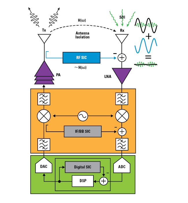
Figure 3 SIC techniques subtract a copy of the transmit signal from the receiver signal. It can be implemented at RF, IF, BB or after data conversion.
The prevailing method for implementing analog SIC is to tap off a portion of the Tx signal, process it so that it has the same magnitude but opposite polarity as the leakage, then inject it back into the receiver input to cancel the transmitter leakage. As this is a vector cancellation, the canceller must accurately replicate the magnitude and phase of the self-interference (SI) channel’s transfer function over the system’s instantaneous bandwidth. In narrowband systems, the canceller circuitry can be as simple as a phase shifter and attenuator, set to match the amplitude and phase of the SI channel. However, this generally only provides cancellation at a single frequency or narrow band, since the group delay of the SI path causes the phase of the SI path and the canceller path to diverge as the frequency range widens.
Several wideband cancellers have recently been demonstrated, using technologies such as coaxial delay lines and switched-capacitor delay lines to match the delay of the SI path. Several of these implementations contain multiple signal paths, each with its own delay and weight. This allows the canceller to account for multiple SI coupling paths, such as where near-field scattering objects result in multipath coupling with a non-zero spread in delay values. Other implementations use frequency-domain equalization, in which multiple narrowband filters with configurable amplitude, phase and delay are combined to approximate the amplitude and phase of the SI path transfer function over a given bandwidth. Combined analog SIC at both RF and BB has yielded 30 to 50 dB of cancellation across 20 to 100 MHz bandwidths.2-4 Combined with antenna isolation, this is often sufficient to prevent saturation of the receiver; however, it rarely provides enough total isolation to facilitate same frequency STAR.
Digital SI is the last method used to cancel undesired Tx leakage. Digital cancellation operates much like analog cancellation: it passes the known Tx waveform through a digital filter which emulates the SI coupling channel’s transfer function, then subtracts the resulting signal from the receiver input. Digital SIC is inherently more flexible than analog cancellation because it can perform a variety of signal processing functions without adding noise or distortion. A primary limitation of digital SIC is it relies on the self-interference being digitized without prior distortion or damage in the receiver. It is not a substitute for the various analog methods of SIC, rather a complementary approach which can help achieve the > 100 dB total isolation required for STAR/IBFD. A second drawback of digital SIC is its increasing complexity as signal bandwidth increases. Digital SIC has been demonstrated to nearly 100 MHz signal bandwidths, but it has not achieved the > 1 GHz signal bandwidths required by many military systems.
COMMERCIAL VS. DEFENSE
Researchers have made incredible progress toward IBFD communications systems for commercial requirements. However, current SIC systems fall significantly short of the performance required for many defense applications. Some defense systems are similar to their commercial counterparts, while others have performance requirements far beyond those of typical commercial systems. Examples include:
Instantaneous bandwidth - State-of-the-art SIC circuits provide relevant levels of Tx/Rx isolation to approximately 100 MHz instantaneous bandwidth.5 These bandwidths are sufficient for many commercial communications applications, which have typical channel bandwidths from 20 to 80 MHz. With the advent of multi-GSPS analog-to-digital converters, many defense systems require SIC over several GHz of instantaneous bandwidth—orders of magnitude greater than current SIC systems. One of the main challenges to achieving cancellation over these bandwidths is realizing compact, low loss delay elements that match the delay of the physical coupling distance between Tx and Rx antennas. SIC circuits require variable delay elements with large delay range and fine resolution to match complex multipath antenna coupling environments, yet current variable delay elements pose unfavorable tradeoffs among size, loss and bandwidth.
Transmit power handling - The best SIC systems have demonstrated power handling less than 30 dBm.3 While this is acceptable for certain low power applications, such as cellular handsets and local wireless networks, many defense requirements exceed current capabilities by orders of magnitude, i.e., Tx powers from 40 to 60 dBm.
Frequency agility - Commercial systems typically operate on fixed, predefined frequency bands. This bounds the solution space for SIC systems, significantly reducing the complexity to a prescribed frequency and instantaneous bandwidth. Military systems, however, are trending to wideband frequency agility: certain communication systems must support multi-band operation spanning wide frequency ranges. Low probability of intercept radar and secure communications rely on frequency hopping or other frequency-agile methods. EW systems must be configured to cover many frequency bands to provide threat monitoring and mitigation over the full spectrum.
Multipath environments - SIC systems must cancel reflections from nearby scattering objects, as these reflections can have similar magnitudes to the direct coupling between antennas. These complex multipath environments present challenges when there is a large spread in the delays among the various coupling and scattering paths. The SIC circuitry must produce equivalent delays to those of the coupling paths, and it is challenging to create the required delays in a compact, low loss form.
Doppler shift - SIC in the presence of multipath is further complicated when the environment surrounding the antennas is not static. Variation of the coupling environment over time poses multiple challenges. First, it places a limit on the reconfiguration speed of the cancellation system, as the SIC must adapt to the coupling environment at roughly the same rate as the environment changes. Time-varying multipath can introduce Doppler frequency shifts, depending on the wavelength of interest and the velocity of the time-varying object. Helicopter rotors and aircraft propellers are common items that can create micro-Doppler sidebands on the SI signal (see Figure 4). For example, a typical 20 m diameter helicopter rotor rotating at 250 revolutions per minute creates a Doppler shift of some 9 kHz on a 10 GHz carrier. These Doppler sidebands add significant complications, as the cancellation hardware must either match the frequency shift with circuitry that translates the frequency or senses the channel phase variations and quickly updates the hardware.
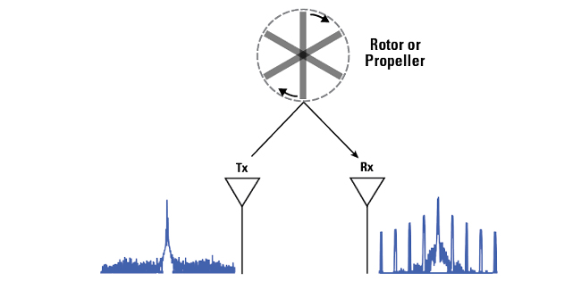
Figure 4 Rotating scattering objects can introduce micro-Doppler sidebands to the received signal, complicating SIC.
DoD RESEARCH
The U.S. Department of Defense (DoD) has invested heavily in wideband, high-power, widely reconfigurable RF devices and systems over the past several decades. Examples include DARPA Microsystems Technology Office programs such as RF Field-Programmable Gate Array (RF-FPGA), Technologies for Mixed-mode Ultra Scaled Integrated Circuits (T-MUSIC), Arrays at Commercial Timescales and Signal Processing at RF (SPAR). The maturity of STAR capabilities has not kept pace with these advancements, leaving a capabilities gap with many current and future systems.
The path to closing this gap requires a substantial investment to address the challenges outlined in this article. Approaches may include the development of new RF materials with higher power handling or lower loss, new circuit architectures breaking the fundamental tradeoffs between group delay and bandwidth, frequency-translational architectures which enable cancellation of Doppler SI or fast closed-loop control algorithms adapting to rapidly-changing antenna coupling environments. Recognizing this critical technology gap, the DoD recently began investing in scaling the performance of STAR technologies to the levels required by military systems. The DARPA Wideband Adaptive RF Protection (WARP) program is the most recent example, accompanied by several SBIR/STTR programs sponsored by various services.
BAE Systems is focused on advanced electronics for DoD applications, with a rich portfolio of advanced defense electronics programs such as DARPA RF-FPGA, CONCERTO, T-MUSIC and others. The company was recently awarded two contracts on the DARPA WARP program to develop widely-tunable filters and broadband SIC cancellation systems, which are addressing many of the issues described in this article. The capabilities developed on these programs will enable interference mitigation capabilities for BAE Systems’ suite of advanced reconfigurable RF electronics and provide more capable and robust systems to protect the warfighter.
References
- K. E. Kolodziej, P. T. Hurst, A. J. Fenn and L. I. Parad, "Ring Array Antenna with Optimized Beamformer for Simultaneous Transmit and Receive,” Proceedings of the 2012 IEEE International Symposium on Antennas and Propagation, Chicago, Ill., 2012, pp. 1–2.
- A. Nagulu et al., "A Full-Duplex Receiver with True-Time-Delay Cancelers Based on Switched-Capacitor-Networks Operating Beyond the Delay-Bandwidth Limit,” IEEE Journal of Solid-State Circuits.
- K. E. Kolodziej, B. T. Perry and J. S. Herd, "In-Band Full-Duplex Technology: Techniques and Systems Survey,” IEEE Transactions on Microwave Theory and Techniques, Vol. 67, No. 7, July 2019, pp. 3025–3041.
- A. El Sayed et al., "A Full-duplex Receiver with 80 MHz Bandwidth Self-interference Cancellation Circuit using Baseband Hilbert Transform Equalization,” IEEE Radio Frequency Integrated Circuits (RFIC) Symposium, Honolulu, Hawaii, 2017, pp. 360–363.
- D. Korpi, M. Heino, C. Icheln, K. Haneda and M. Valkama, "Compact Inband Full-Duplex Relays With Beyond 100 dB Self-Interference Suppression: Enabling Techniques and Field Measurements,” IEEE Transactions on Antennas and Propagation, Vol. 65, No. 2, February 2017, pp. 960–965.