

The test uses tone frequencies of 869 and 891.5 MHz with an IM measurement of the lower sideband at 846.5 MHz. The PIM tester generates two 20 W test tones (2 x 43 dBm), which are reduced 6 dB in the test fixture by the low PIM, high power attenuator shown in Figure 5. The resulting test tone levels of 5 W (2 x 37 dBm) are applied to the DUT input. The MM5130 SP4T MEMS RF switch is rated to 25 W continuous, and testing at 2 x 5 W is well within its operations rating.
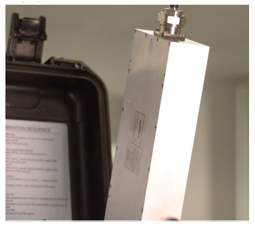
Figure 5 High power, low PIM 6 dB attenuator.
The DUT is the MM5130 SP4T MEMS RF switch mounted on its EVK PCB and connected using low PIM connectors, (see Figure 6). Each of the four RF switches have separate connectors with the fifth connector being the common RFC. The EVK includes a USB driver interface for switch control and requires the 90 V gate supply to be sourced externally from a programmable power supply.
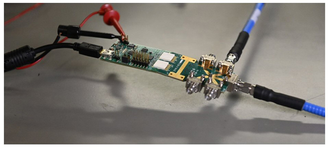
Figure 6 Menlo Micro MM5130 SP4T MEMS RF switch EVK cabled for testing Switch 1.
A close-up view of the MM5130 switch mounted on the EVK is shown in Figure 7. The device is a glass package with the MEMS switch structures visible inside.
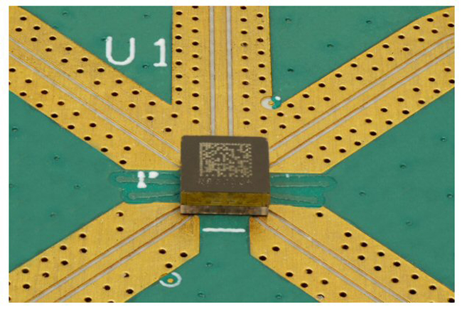
Figure 7 MM5130 SP4T MEMS RF switch mounted on the EVK PCB.
Forward IM is measured using a duplexer and filter (see Figure 8). The three-port duplexer separates the fundamental tones from the lower sideband IM product. The IM bandpass filter provides 95 dB rejection for measurement of forward IM. Reverse IM, normally measured in the PIM tester, is output from the PIM tester for measurement by a spectrum analyzer. The control panel selection of reverse or forward path configures the coaxial relay accordingly. Spectrum analyzer measurements are read by the control panel, are visually displayed and IP3 is computed.
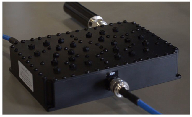
Figure 8 Three-port duplexer with termination and filtered IM output ports.
An example measurement is illustrated in Figures 9 and 10 focusing on the control panel array of IP3 measurements for each MM5130 switch channel and the IM3 sideband plot for the current measurement. Automated IP3 testing can be configured to run voltage and temperature characterization over multiple devices and lots.
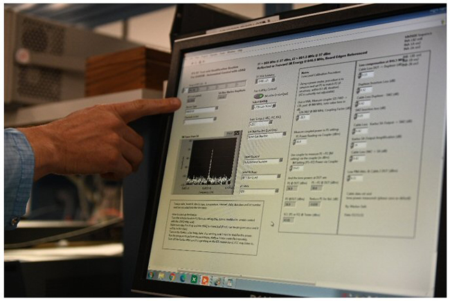
Figure 9 Control panel display of measurement results.
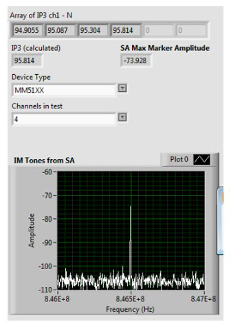
Figure 10 MM5130 IP3 measurement results for all four channels showing typically +95 dBm.
From the measured single sideband IM of – 73.928 dBm, the corrected IM at the DUT is found by subtracting a net path gain of 6.99 dB for a corrected IM of – 80.92 dBm. IM3 computed from the SCL of 36.9 dBm is 117.82 dBc. From Equation (1), IP3 is 117.82/2 + 36.9 dBm = 95.8 dBm, corresponding to the last switch tested in Figure 10.
CONCLUSION
IP3 measurement of low PIM devices requires high test tone power levels and sensitive instrumentation to measure the resulting IM sidebands. Successful measurement requires the setup to be constructed using low PIM components and carefully calibrated for tone level and path loss. Automation software facilitates characterization over temperature and voltage and is suitable for lot level testing.
Modern communications systems, from 5G infrastructure cells to wideband military radios, demand increasing levels of RF subsystem and component performance. Presented are some of the challenges in measuring very high levels of 3rd order intermodulation products, particularly for ultra-low loss and highly linear passive devices. Paying careful attention to test equipment and accurate characterization of all components ensures stable IP3 measurements can be achieved on high performance devices.