
The ability to benchmark the performance of semiconductor technologies using small periphery devices, quickly and accurately, can reduce development cost and expedite time to market. This can now be achieved using hybrid-active vector receiver load-pull measurements that enable E- and W-Band device characterization up to gamma magnitudes of 1 at the device-under-test (DUT) reference plane.
Much of the next generation of wireless technologies for mobile, satellite, automotive and radiolocation are being designed to operate in the upper mmWave bands of 70 to 110 GHz. For mobile and satellite, this means 10x to 100x more available unlicensed spectrum compared to the sub-10 GHz bands, leading to increased data bandwidth, transmission rate and data throughput. For automotive applications and radiolocation, mmWave frequencies provide higher imaging resolution and improved intra- and inter-vehicle communications. This enables applications such as automotive radar, collision avoidance and traffic information exchange between vehicles.
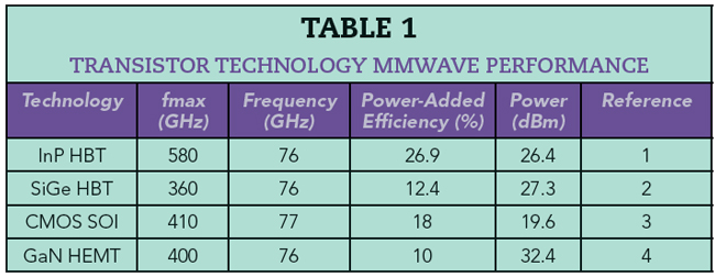
Designing solutions to work effectively and efficiently in these frequency bands is not a simple task. It is especially challenging to design mmWave circuitry, such as transmitters and receivers, which include amplifiers to boost signal power levels. Active components are critical to achieving the required performance. Some of the biggest challenges to overcome are the low gain, output power and efficiency of transistors at these frequencies. To address these limitations, multiple technologies have been developed (see Table 1). While these semiconductor technologies offer good performance for applications in the 20 to 40 GHz range,5 i.e., the 5G FR2 range, transistor performance drops as frequency increases, limiting their use for applications over 70 GHz. This is due to the device parasitics becoming significant at E- and W-Bands. The cutoff frequency (ft) of a device should ideally be about 10x the target operating frequency for the device not to become one of the major limiting factors in a high efficiency power amplifier design. So it is critical to optimize the circuit design to squeeze out every last tenth of a dB of gain, dBm of output power and percent of efficiency.
Optimal circuit design can only be realized with accurate device models or fully characterized transistors. While a robust mmWave device model is often available for a mature device technology, newer modeling approaches can use accurate device reference plane measurements to develop device models for less mature technologies.6 mmWave device models based on neural networks, for example, may offer an advantage compared to the current modeling paradigm.
Load-pull, the technique of systematically varying the reflection coefficient (ΓL) at the output of a DUT and measuring changes in its performance, is a practical method for extracting and validating models and for performing small- and large-signal device characterization. A common consideration when performing load-pull at E- and W-Band is choosing the size of device to characterize. Performing load-pull on devices with small peripheries - less than four fingers - results in lower fabrication costs and time and contributes to faster time to market and higher profitability.7 The small periphery, however, usually has high device S11 and S22. This makes characterization challenging because ΓL > 0.9 at the DUT reference plane is required to fully characterize the device. Conventional tuner-based load-pull setups struggle to achieve ΓL = 0.7 at the DUT reference plane, limited by high insertion loss of the RF probes connecting the test system to the DUT. As such, designers tend to fabricate larger devices with more than four fingers8 or include pre-matching circuitry9 to lower the ΓL required to characterize DUTs. This, however, increases fabrication cost and time, which can delay technology development and time to market.
Recent advances in measurement technology and instrumentation have enabled hybrid-active vector receiver load-pull for high- power, mmWave device characterization, including the 70 to 110 GHz bands discussed here.
HYBRID-ACTIVE LOAD-PULL
Consider a two-port network where the waves incident to and reflected by the network are denoted as ax and bx, respectively, where x denotes the network port. This network has an input reflection coefficient Γin = b1/a1 and a load reflection coefficient defined as ΓL = a2/b2. Load-pull characterization enables the user to systematically vary ΓL presented to the DUT while measuring a multitude of device parameters versus drive power at each impedance state. Passive load- pull10 uses mechanical impedance tuners to change the magnitude and phase of the reflected signal a2 and vary the ΓL presented to the DUT. This is accomplished by moving a probe up, down, left and right along a 50 Ω airline (see Figure 1a). |ΓL| will always be < 1, since a2 will always be smaller due to losses between the output of the DUT and the tuner. Open-loop active load-pull systems10 do not rely on a mechanical tuner to reflect part of b2 back as a2. Instead, they use active signal injection with magnitude and phase control to create a new signal a2 (see Figure 1b). When amplified by an external amplifier, any a2 and any ΓL can be achieved.

Figure 1 Mechanical tuner (a) and active loop (b) load-pull measurement.
Active tuning has several advantages over passive tuning, including faster speed and increased coverage of the Smith chart. This is because there are no mechanical moving parts, and the actively generated a2 wave can be used to set |ΓL| > 1. The challenge with active tuning is the availability of driver amplifiers to boost the a2 signal. Typically, they are required to have 5x to 10x higher output power than the DUT due to the mismatch between the DUT output impedance and the nominal 50 Ω impedance of the driver amplifier. A modified approach, hybrid-active load-pull, overcomes this challenge by pre-matching the DUT impedance with a passive impedance tuner, which lowers the driver amplifier output power required to deliver the same signal a2 to the output of the DUT (see Figure 2).
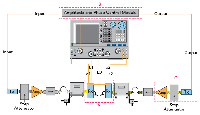
Figure 2 W-Band hybrid-active load-pull measurement system.