
With emerging fifth generation (5G) cellular communication systems, the demand for passive components is driving the growth of massive MIMO and carrier aggregation technologies. With this growth, microwave filters are faced with a number of technical challenges including miniature sizing with a demand for better electromagnetic performance such as lower passband loss, sharper skirts and higher isolation without increasing manufacturing costs. Ceramic waveguide filter design using different dielectric materials is well researched.1, 2 More recently, Afridi et al.3 studied miniaturization by using evanescent modes to provide a wide spurious-free window. Compared to a traditional metallic or dielectric resonator filter, the ceramic-filled waveguide filter offers lower loss, higher power handling capability and a wider spurious-free window while also meeting miniature size requirements. In this article, we describe a procedure to design a dielectric-filled waveguide filter using advanced computer-aided tuning techniques.
DESIGN
Resonator Analysis
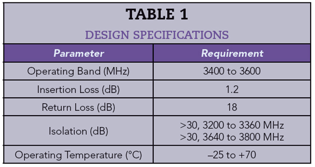
To meet the specifications in Table 1, a ceramic material with a dielectric constant of 21.2 and loss tangent of 7.45e-5 is selected. A waveguide resonator can be treated as a truncated section of rectangular waveguide with a length of half the guided wavelength with conducting boundaries on all of its walls. By filling the cavity with a material of dielectric constant εr, its dimensions are reduced by a factor of  .
.
The fundamental TE mode resonant frequency of a half wavelength ceramic waveguide resonator is determined by:4
where l, m and n represents the half wavelength variation of electric field lines along the width (a), height (b) and length (d) of the resonator, respectively.
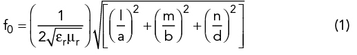
The resonant frequency is dependent only on the waveguide width and length while the unloaded Q and higher order spurious are bounded by the waveguide height; a shorter height provides a wider spurious-free window, while a taller height provides a higher Q. By optimizing waveguide dimensions, engineers can, therefore, trade off unloaded Q, resonant frequency and the size of the “clean” or spurious-free window of operation (see Figure 1). This is illustrated by electromagnetic simulation (see Figure 2a) using the ANSYS HFSS eigenmode solver.5 It can be seen that the TE102 mode occurs at 6000 MHz and the unloaded Q value is about 2600, which is very close to the theoretical result.
For this design, a = 12 mm, b = 6 mm and d = 12 mm. The dimensions are chosen to compensate for the electrical field variation due to the tuning mechanism on the top wall (see Figure 2b). The resonator is silver plated. For design modeling, the resonator unloaded Q is assumed to be a conservative 70 percent of the simulated result, or 2000, to provide margin.
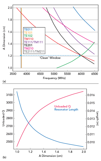
Figure 1 Mode (a) and corresponding unloaded Q (b).
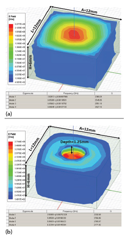
Figure 2 ANSYS HFSS EM simulation without (a) and with (b) tuning.
Matrix Synthesis and Coupling
The coupling matrix is generated using the SynMatrix platform which integrates coupling matrix synthesis and computer-aided tuning tools.6 Coupling matrix synthesis is an iterative optimization process for achieving the best performance within a safe design margin; it is also a comprehensive process that considers power handling capability, tuning sensitivity, thermal shift electrical impact, physical realization and manufacturing sensitivity. For example, to improve insertion loss (IL) by flattening ripple variation, the bandwidth must be widened, which can negatively impact isolation. From a mechanical perspective, different topologies will result in different power handling capabilities. A cascade quadruplet (CQ) has a more uniform, even distribution than the cascade triplet (CT) with the same electrical performance. However, the CT structure is a more favorable engineering design because of its flexible tuning capabilities and the ease of realizing its physical structure.
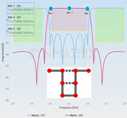
Figure 3 Filter topology and performance after synthesis.
Figure 3 shows the final filter performance and its corresponding topology using the SynMatrix synthesis tool. In this design, an eight pole folded CQ topology is used due to its physical compactness. One can realize the maximum transmission zeros with limited space by using this topology. The corresponding coupling matrix with a 10 MHz bandwidth extension is shown below:
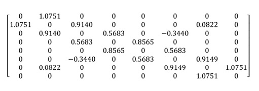
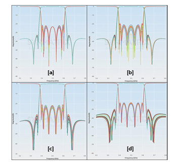
Figure 4 Monte-Carlo analysis of the coupling matrix, showing 1 percent variation of the self-coupling (a), main coupling (b), M25 (c) and M16 (d).
Design margins must account for temperature variations to compensate for thermal drift. For a conservative design margin, a material coefficient of thermal expansion of -0.4 ppm/°C and a temperature range between -40° to +100°C is used. Note that IL performance is gained by extending the bandwidth.
To ensure stability, a Monte-Carlo method is used to analyze the coupling matrix and find the most sensitive element. This provides useful information during the post simulation and tuning process. In this work, Monte-Carlo analysis is used to detect changes within 1 percent for self-coupling, main coupling and the transmission zeros M2,5 and M1,6 (see Figure 4). Within 1 percent error control, the overall performance meets the specification.