
Editor’s Note: In Part III, the authors describe methods to reduce stiction effects in the capacitive (metal-insulator-metal) contact MEMS switch for applications in low SNR signal routing application in modern electronics circuits including 5G communication. Also, experimental results to validate simulation results presented earlier for DSG structure-based metamaterial switch are also included in this paper. As described in Part I (May Issue), the combination of a primary shunt switch, DGS structures and secondary shunt switches, is shown to behave like a metamaterial. In Part II, the authors have shown new ways to reduce stiction effects in the Resistive MEMS switch (metal-to-metal contact) using artificially created metamaterial structure.
The theory of a repulsive Casimir force and application in a resistive contact MEMS switch is discussed in detail in Part II (June Issue). In this article, a new method to reduce the stiction effects in the capacitive (metal-insulator-metal) contact MEMS switch that has applications in low SNR signal routing application in modern electronics circuits including 5G communication is described.1-8 In addition, experimental results to validate simulated results presented earlier for DSG structure-based metamaterial switch are included.
CASIMIR REPULSIVE FORCE INSPIRED CAPACITIVE MEMS SWITCH
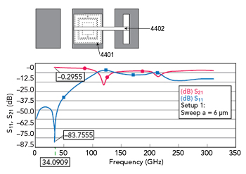
Figure 1 Transmission and reflection characteristics of composite structure described by 4401 and 4402.
The metamaterial unit cell described in reference9 and realized using a composite engineered structure, provides promising characteristics in the relevant band of frequencies for the MEMS switch (e.g., between 60 to 130 GHz). Figures 1 to 3 provide results for transmission and reflection characteristics for a respective unit cell structure. The composite structure, 4401 illustrated in Figure 1, is included in a metal layer (e.g., of a signal line contact) and interfaces beam 4402. In this example, the beam is thinner than the metamaterial structure, and is supported by a single support extending from one of the ground planes adjacent the signal line. The unit cell is a transmission type at about 34 GHz (having reflection characteristics of -83.75 dB and transmission characteristics of -0.29 dB). The unit cell is a reflection type at about 120 GHz. Thus, the composite structure in Figure 1 is shown to exhibit metamaterial properties, can be used for the realization of stiction free capacitive (metal-insulator-metal) contact MEMS switch.
The composite structure (4501) shown in Figure 2 is included in a metal layer (e.g., of a signal line contact) and interfaces with beam 4502. In this example, the beam is thinner than the metamaterial structure, and is doubly supported by posts on either side of the signal line. The unit cell is a transmission type at about 40 GHz (having reflection characteristics of -54 dB and transmission characteristics of -0.5 dB). The unit cell is a reflection type at about 140 GHz. Thus, the structure of Figure 2 is shown to exhibit metamaterial properties also, hence can be used for the realization of stiction free capacitive (metal-insulator-metal) contact MEMS switch.
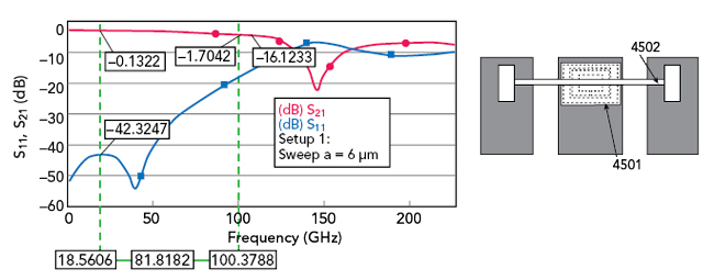
Figure 2 Transmission and reflection characteristics of composite structure described by 4501 and 4502.
Figure 3 includes two composite structures, 4601 and 4603, positioned at opposing input and output sides of the signal line. Each composite structure is included in a metal layer (e.g., of the signal line contact). Further, doubly supported beams, 4602 and 4604, are positioned above each of the composite structures. As in the example of Figure 2, the beams are thinner than the metamaterial structures. The unit cell is a transmission type at about 8 GHz (having reflection characteristics of -60 dB and transmission characteristics of -0.01 dB). The unit cell is a reflection type at about 160 GHz. Thus, the structure of Figure 3 is shown to exhibit metamaterial properties too, hence can be used for the realization of stiction free capacitive (metal-insulator-metal) contact MEMS switch.
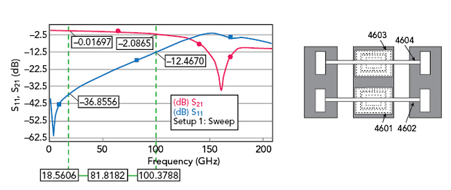
Figure 3 Transmission and reflection characteristics of composite structure described by 4601 and 4602.
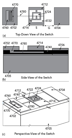
Figure 4 Diagram of capacitive MEMS switch incorporating metamaterial cells to provide a repulsive Casimir Force between contacts of switch: (a) top-down view, (b) side view and (c) perspective view.
Another example of a capacitive MEMS switch is shown in Figure 4. As illustrated in Figure 4, the switch includes a structure formed over a signal line having an input side 4712 and an output side 4714. A metamaterial structure having an outer split ring 4722 and inner split ring 4724 is formed in the signal line contact between the input side 4712 and output side 4714, through which a signal is received (arrow in) and an output port through which the signal is transmitted (arrow out).
Each of the ground planes 4702, 4704 and the signal line are formed from a conductive material, such as gold, and are formed on top of a dielectric material 4740 such as silicon nitride (Si3N4), which itself is formed on top of a substrate 4705. One of the ground planes 4702 includes a post 4770 extending downward from the ground plane 4702 into the dielectric material 4740, and a beam 4780 extending from the post 4770 in the direction of the signal line 4714. The edge of the beam 4780 is aligned with the opposing edge of the signal line 4712, 4714, such that the end of beam 4780 is positioned underneath the metamaterial structures 4722, 4724, of the signal line 4712, 4714. In Figures 4a and 4c, the post 4770 can be seen through an opening 4760 in the ground plane 4702.
In the example of Figure 4, the ground planes and the signal line may each have a width (in the direction of the beam 4780 length) of about 73 μm and the beam may have a length of about 168 μm. The metamaterial structure formed on the signal line contact may have a ring width W of about 15 μm, a split width G of about 8 μm and a spacing between rings S of about 5 μm.
Transmission and reflection characteristics of the switch over a range of frequencies are shown in Figure 5. The metamaterial is most reflective at about 175 GHz and most transmissive at about 80 GHz. Based on these results, material parameter extraction10 can be performed to determine the permittivity and permeability of the metamaterial structure. The extraction of the permeability and permittivity are shown over a range of frequencies in Figure 6.
As seen in Figure 6, the metamaterial structure exhibits near zero permittivity and permeability between about 50 and 150 GHz. This indicates that the structure of Figure 4 is suitable for reducing the stiction using the Casimir force of interaction (repulsive) in the desired frequency band.
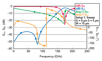
Figure 5 Transmission and reflection characteristics of capacitive MEMS switch in Figure 4.
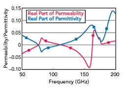
Figure 6 Plot of permittivity extracted from the S-parameters of the composite structure shown in Figure 4.
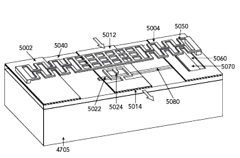
Figure 7 Perspective view of a capacitive shunt MEMS switch utilizing a metamaterial signal line contact to reduce stiction in the switch.
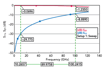
Figure 8 Transmission and reflection characteristics of capacitive MEMS switch shown in Figure 7 in the ON State.
Figure 7 shows a perspective view of a capacitive shunt MEMS switch utilizing a metamaterial signal line contact to reduce stiction in the switch. Many of the features of switch illustrated in Figure 7 may be compared to the switch described in Figure 4. The switch in Figure 7 also includes a deflectable beam 5050. The beam is comparable to the rectangular beam 510 described in connection with Figure 5 of Part I (May Issue) (e.g., may be made from gold, may have a perforated grid structure, may extend in a serpentine pattern). The deflectable beam 5050 is supported by a pair of posts formed on top of the ground planes 5002 and 5004, respectively, and is configured to deflect downward toward the signal line when actuated by a bias voltage.
In operation, the bias voltage causes the midpoint of the beam 5050 to deflect downward until it comes in contact with the signal line contact, thereby causing the signal line to turn off (or in other cases to turn on). When the bias voltage is removed, the midpoint of the beam 5050 deflects back upward. Because the midpoint of the beam is aligned with the metamaterial structure 5022, 5024 of the signal line contact, the Casimir effect at the interface between the beam and the signal line contact is diminished or even repulsive, thereby reducing the liability of stiction between the beam 5050 and the signal line.
Although not shown in Figure 7, the signal line contact can include a layer of dielectric material above the metal layer including the metamaterial structure. The dielectric layer can function as an isolation layer to achieve the desired permittivity gradient, as discussed above in connection with Figure 5 (Part II, June Issue). In other words, the beam 5050 can have an infinite permittivity, the isolation layer can have a positive but smaller permittivity and the metal layer including the metamaterial structure in the signal line contact can have a near zero, zero or negative permittivity, thereby satisfying ε1<ε2<ε3 condition or vice-versa. The performance of the capacitive MEMS switch (Figure 7) is shown in Figures 8 and 9 which are plots of the reflection and transmission characteristics of the switch across a range of high RF frequencies. Figure 8 demonstrates operation of the switch in the ON state (transmitting signals) and Figure 9 demonstrates operation of the switch in the OFF state (cutting off transmission of signals).
In Figure 8, most notably, at 10.3 GHz, return loss is as high as 29.8 dB while insertion loss is as low as about 0.07 dB. Even at 100.2 GHz, return loss is as high as 8.9 dB while insertion loss is only about 1.23 dB. This demonstrates good operation of the switch in the ON state across a wide range of high frequencies, from 10 to 100 GHz.
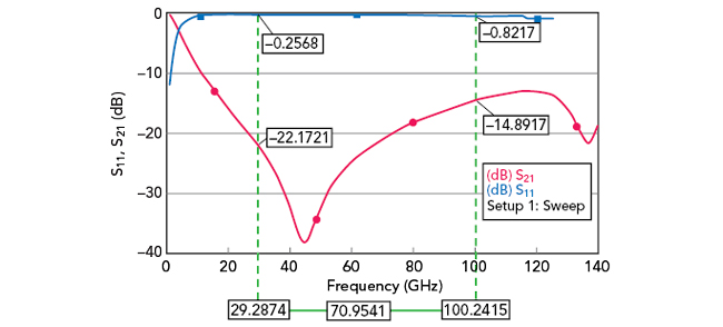
Figure 9 Transmission and reflection characteristics of capacitive MEMS switch shown in Figure 7 in the OFF State.
In Figure 9, the switch is OFF, thus changing to being reflective instead of transmissive. At 29.3 GHz, insertion loss is as high as about 22.2 dB while return loss is as low as about 0.26 dB. Even at 100.2 GHz, insertion loss is as high as 14.9 dB while return loss is only about 0.82 dB. This demonstrates good operation of the switch in its OFF state across nearly the same wide range of high frequencies, from about 20 to 100 GHz.
Good insertion loss and return loss characteristics of the MEMS switch in the ON and OFF states are achieved over 30 to 100 GHz. This makes the presently described switch a good candidate for high frequency switching operations over a wide bandwidth of frequencies. Accordingly, the switches described can improve operation and performance of applications requiring high frequencies over a wide bandwidth. Such technologies may include 5G communications, switching networks, phase shifters (e.g., in electronically scanned phase array antennas) and IoT applications.
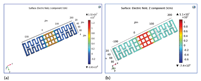
Figure 10 Electric field distribution of a shunt switch with serpentine signal line and (a) with and (b) without metamaterial.